Safety
Information
Product
information
Mechanical
installation
Electrical
installation
Getting
started
Basic
parameters
Running the
motor
Optimization
EtherCAT
interface
SMARTCARD
Operation
Onboard
PLC
Advanced
parameters
Technical
Data
Diagnostics
UL listing
information
Digitax ST User Guide 17
Issue: 5
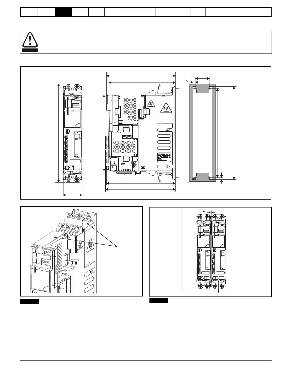
3.4 Drive dimensions
The drive complies with the requirements of IP20 as standard.
Figure 3-5 Dimensions
Figure 3-6 Ingress protective label
The ingress protective labels (shown on Figure 3-6 above) should
remain in place while the drive is mounted, and until all the electrical
wires have been connected. The labels should be removed before first
power up.
Figure 3-7 Minimum mounting clearances
*2 mm clearance between drives to allow for mechanical tolerance.
If Solutions Modules are installed, a larger clearance between drives will
be required if access to the modules is needed without removing the
drive.
Enclosure
The drive is intended to be mounted in an enclosure which prevents access except by trained and authorized personnel, and which
prevents the ingress of contamination. It is designed for use in an environment classified as pollution degree 2 in accordance with IEC
60664-1. This means that only dry, non-conducting contamination is acceptable.
62mm
(2.44in)
249.7mm
(9.83in)
220mm (8.66in)
47mm
(1.85in)
∅
5.4mm (0.21in)
M5
322mm
(12.68in)
226mm (8.9in)
226mm (8.9in)
229mm (9.02in)
Ingress protective labels

 Loading...