Safety
Information
Product
information
Mechanical
installation
Electrical
installation
Getting
started
Basic
parameters
Running the
motor
Optimization
EtherCAT
interface
SMARTCARD
Operation
Onboard
PLC
Advanced
parameters
Technical
Data
Diagnostics
UL listing
information
24 Digitax ST User Guide
Issue: 5
4.4 DC bus design
4.4.1 DC bus design
Parallel connections
The power limit of the rectifier must be adhered to for all combinations of
drives in parallel. In addition to this If the total rated bus power required
exceeds the capability of 1 x Digitax ST rectifier then two or more Digitax
ST's can be connected with the AC & DC in parallel. If the AC supply is
connected to more than one drive in a parallel DC bus application,
balancing of the current in the input stage of each drive must be
considered.
Using DC bus chokes makes the current in the rectifier diodes of each
drive the same, so providing a solution to sharing.
There are many possible combinations for paralleling drives through the
DC bus connections. Table 4-3 gives details of the internal capacitance
for each drive and the additional capacitance which can be powered
from the drive. The capacitance must incorporate its own soft-start
circuit. All Digitax ST drives incorporate this feature.
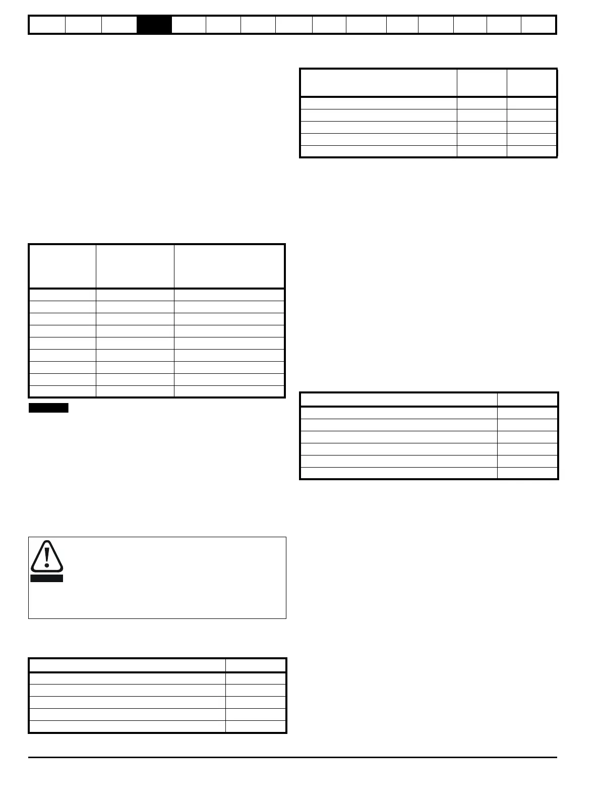
Table 4-3 DC bus data
For additional details regarding DC bus paralleling please contact the
supplier of the drive.
4.5 DC drive voltage levels
4.5.1 Low voltage DC operation
The drive can be operated from low voltage DC supplies, nominally 24
Vdc (control) and 48 Vdc (power). The low voltage DC power operating
mode is designed either, to allow for motor operation in an emergency
back-up situation following failure of the AC supply, for example in
robotic arm applications; or to limit the speed of a servo motor during
set-up of equipment, for example a robot cell.
The working voltage range of the low voltage DC power supply is shown
in Table 4-4.
Table 4-4 Low voltage DC levels
4.5.2 High voltage DC levels
Table 4-5 High voltage DC levels
* These are the absolute minimum DC voltages that the drive is capable
of operating from. If the drive is not supplied with the minimum voltage, it
will not reset following a UV trip at power-up.
4.5.3 Control 24 Vdc supply
The 24 Vdc input has three main functions:
• It can be used as a back-up power supply to keep the control circuits
of the drive powered up when the line power supply is removed. This
allows any fieldbus modules or serial communications to continue to
operate.
• It can be used to supplement the drive’s own internal 24 V when
multiple SM-I/O Plus modules are being used and the current drawn
by these modules is greater than the drive can supply. (If too much
current is drawn from the drive, the drive will initiate a 'PS.24V' trip)
• It can be used to commission the drive when line power supply
voltages are not available, as the display operates correctly.
However, the drive will be in the UV trip state unless either line
power supply is reapplied or low voltage DC operation is enabled,
therefore diagnostics may not be possible. (Power down save
parameters are not saved when using the 24 V back-up power
supply input.)
The working voltage range of the 24 V power supply is shown in Table 4-6.
Table 4-6 Control supply voltage levels
Minimum and maximum voltage values include ripple and noise. Ripple
and noise values must not exceed 5 %.
Drive
Internal DC bus
capacitance
(μF)
Maximum additional DC
bus capacitance which can
be connected
(μF)
DST1201 440 1760
DST1202 880 1320
DST1203 880 1320
DST1204 1320 880
DST1401 220 660
DST1402 220 660
DST1403 220 660
DST1404 220 660
DST1405 220 660
With low voltage DC operation there is a reduction in the
level of safety of the Safe Torque Off function. There
exist certain unlikely faults which might permit the drive to
produce some limited motor torque, if the DC supply has its
negative terminal connected to ground.
See section 4.17 Safe Torque Off on page 42 for methods
on preventing a loss of the safety function under these
conditions.
Condition Value
Minimum continuous operating voltage 36 V
Minimum start up voltage 40 V
Nominal continuous operating voltage 48 V to 72 V
Maximum braking IGBT turn on voltage 63 V to 95 V
Maximum over voltage trip threshold 69 V to 104 V
Condition
DST120X DST140X
VV
Undervoltage trip level 175 330
Undervoltage reset level* 215 425
Overvoltage trip level 415 830
Braking level 390 780
Maximum continuous voltage level for 15 s 400 800
Condition Value
Maximum continuous operating voltage 30.0 V
Minimum continuous operating voltage 19.2 V
Nominal operating voltage 24.0 V
Minimum start up voltage 21.6 V
Maximum power supply requirement at 24 V 60 W
Recommended fuse 3 A, 50 Vdc

 Loading...