Safety
Information
Product
information
Mechanical
Installation
Electrical
installation
Getting
started
Basic
parameters
Running the
motor
Optimization
SMARTCARD
operation
Onboard
PLC
Advanced
parameters
Technical
data
Diagnostics
UL
information
Mentor MP User Guide 151
Issue: 3 www.controltechniques.com
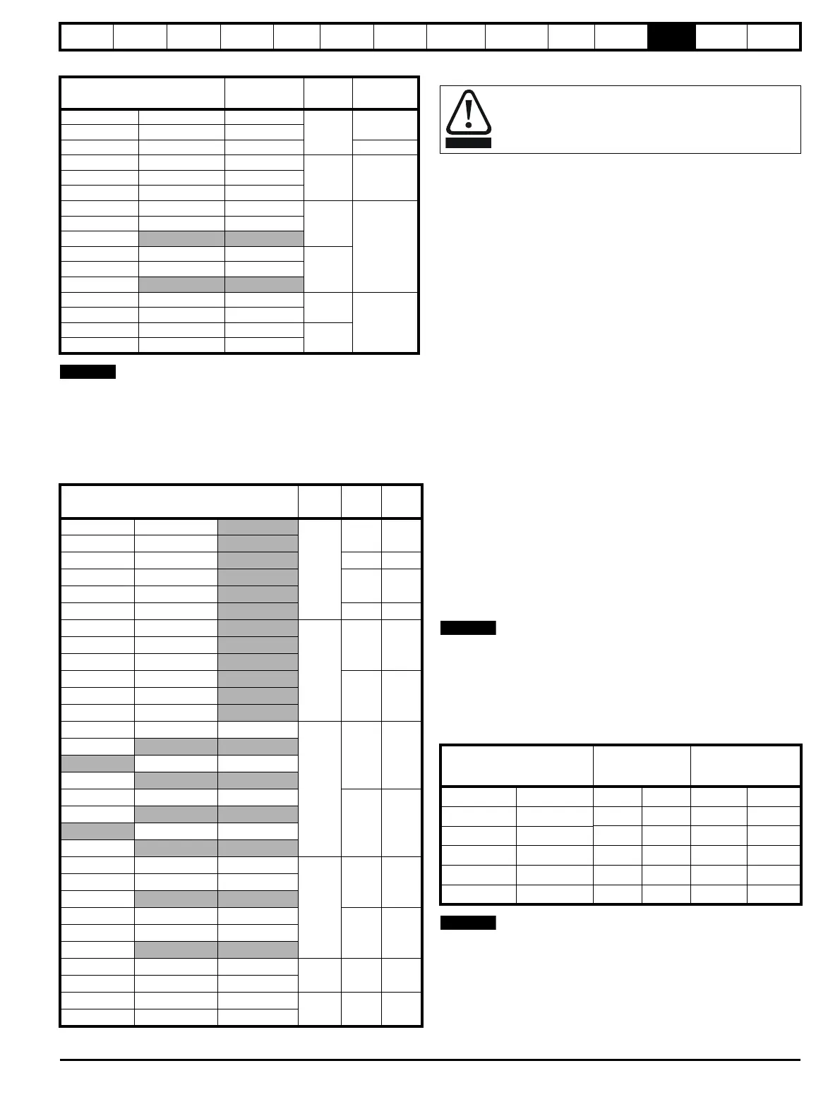
Table 12-9 Acoustic noise data
* The acoustic noise figure for frame sizes 2C and 2D has been taken
with the bottom right angle ducting removed.
12.1.21 Overall dimensions
Refer to section 3.4 Mounting method on page 17.
12.1.22 Weights
Table 12-10 Overall drive weights
12.2 Cable and fuse size ratings
Maximum continuous input currents are given in section 2.1 Ratings on
page 6 to aid the selection of fuses and cabling. The maximum input
current is dependent on the ripple content of the output current. A value
of 100% ripple has been assumed for the given ratings.
The cable sizing selected when installing a Mentor MP must comply with
the local wiring regulations. The information provided in this section is
provided for guidance purposes only.
The power terminals on Mentor MP frame size 1 drives have been
designed to accommodate a maximum cable size of 150mm
2
(350kcmil)
with a temperature of 90°C (194°F).
The power terminals on Mentor MP frame size 2A drives have been
designed to accommodate a maximum cable size of 2 x 150mm
2
(2 x
350kcmil) with a temperature of 75°C (167°F).
The power terminals on Mentor MP frame size 2B drives have been
designed to accommodate 2 x 240mm
2
with a temperature of 90°C
(194°F). The use of cables sized using the US national electrical code as
shown in Table 12-13 requires the use of a terminal adaptor.
The power terminals on Mentor MP frame size 2C and 2D drives have
been designed for use with busbars. The drive can be used with cables
as shown in Table 12-13 with the use of a terminal adaptor.
The actual cable size depends on a number of factors including:
• Actual maximum continuous current
• Ambient temperature
• Cable support, method and grouping
• Cable voltage drop
In applications where the motor used is of a reduced rating, the cable
sizing selected can be appropriate for that motor. To protect the motor
and the output cabling the drive must be programmed with the correct
motor rated current.
When using reduced cable sizes, the branch circuit protection fuse rating
needs to be reduced in line with the cable size selected.
The following table shows typical cable sizes based on USA and
International standards, assuming 3 conductors per raceway/conduit, an
ambient temperature of 40°C (104°F) and applications with high output
current ripple content.
Table 12-11 Typical cable sizes for size 1 drives
1. The maximum cable size is defined by the power terminal housing
using 90°C (194°F) rated cables as per Table A.52-5 of the standard.
2. Assumes the use of 75°C rated cables, as per Table 310.16 of the
National Electrical Code.
The use of higher temperature rated cable would allow a reduction on
the minimum recommended cable size for Mentor MP shown above. For
high temperature cable sizing, please contact the supplier of the drive.
Model
Frame
Size
SPL at 1m
(dBA)
M P 2 5 A 4 ( R ) M P 2 5 A 5 ( R )
1A
No fans
installed
MP45A4(R) MP45A5(R)
M P 7 5 A 4 ( R ) M P 7 5 A 5 ( R ) 4 3
MP105A4(R) MP105A5 (R)
1B 56MP155A4(R) MP155A5(R)
MP210A4(R) MP210A5(R)
MP350A4(R) MP350 A5(R) MP350A6(R)
2A
68
MP420A4(R) MP470A5(R) MP470A6(R)
MP550A4(R)
MP700A4(R) MP700A5(R) MP700A6(R)
2BMP825A4(R) MP825A5(R) MP825A6(R)
MP900A4(R)
MP1200A4 MP1200A5 MP1200A6
2C
67*
MP1850A4 MP1850A5 MP1850A6
MP1200A4R MP1200A5R MP1200A6R
2D
MP1850A4R MP1850A5R MP1850A6R
Model
Frame
size
kg Ib
MP25A4 MP25A5
1A
10 22
MP45A4 MP45A5
MP75A4 MP75A5 10.1 22.3
MP25A4R MP25A5R
10.2 22.5
MP45A4R MP45A5R
MP75A4R MP75A5R 10.5 23.1
MP105A4 MP105A5
1B
12.6 27.8MP155A4 MP155A5
MP210A4 MP210A5
MP105A4R MP105A5R
13.0 28.7MP155A4R MP155A5R
MP210A4R MP210A5R
MP350A4 MP350A5 MP350A6
2A
35 77.2
MP420A4
MP470A5 MP470A6
MP550A4
MP350A4R MP350A5R MP350A6R
38 83.8
MP420A4R
MP470A5R MP470A6R
MP550A4R
MP700A4 MP700A5 MP700A6
2B
41 90.4MP825A4 MP825A5 MP825A6
MP900A4
MP700A4R MP700A5R MP700A6R
46 101.4MP825A4R MP825A5R MP825A6R
MP900A4R
MP1200A4 MP1200A5 MP1200A6
2C 100 220.5
MP1850A4 MP1850A5 MP1850A6
MP1200A4R MP1200A5R MP1200A6R
2D 138 304.2
MP1850A4R MP1850A5R MP1850A6R
The selection of the correct fuse is essential to ensure the
safety of the installation
Model
IEC 60364-5-52
[1]
UL508C/NEC
[2]
Input Output Input Output
MP25A4(R) MP25A5(R)
2.5mm
2
4mm
2
8 AWG 8 AWG
MP45A4(R) MP45A5(R)
10mm
2
10mm
2
4 AWG 4 AWG
MP75A4(R) MP75A5(R)
16mm
2
25mm
2
1 AWG 1/0 AWG
MP105A4(R) MP105A5(R)
25mm
2
35mm
2
1/0 AWG 1/0 AWG
MP155A4(R) MP155A5(R)
50mm
2
70mm
2
3/0 AWG 4/0 AWG
MP210A4(R) MP210A5(R)
95mm
2
95mm
2
300kcmil 350kcmil
 Loading...
