Safety
Information
Product
information
Mechanical
Installation
Electrical
installation
Getting
started
Basic
parameters
Running the
motor
Optimization
SMARTCARD
operation
Onboard
PLC
Advanced
parameters
Technical
data
Diagnostics
UL
information
Mentor MP User Guide 37
Issue: 3 www.controltechniques.com
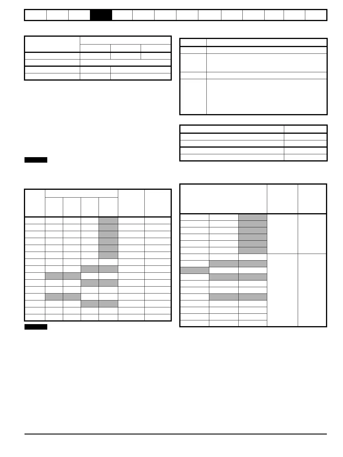
4.3.4 Main AC supply (L1, L2, L3)
Table 4-1 Three phase AC supply
4.4 Line reactors
The Mentor MP, in common with all naturally commutated thyristor
drives, causes voltage notches at the input supply terminals. In order to
avoid disturbance to other equipment using the same supply, the
addition of external line inductance is strongly recommended in order to
restrict the depth of the notches imposed on the shared supply. This is
generally not necessary where a dedicated transformer is used to supply
the drive.
The following recommendations for added line inductance, have been
calculated based on the power drive systems standard: EN 61800-
3:2004 “Adjustable speed electrical power drive systems – Part 3: EMC
requirements and specific test methods”.
The current ratings specified in Table 4-2 are for typical motor currents
where the motor current ripple is no more than 50% of drive rating.
Table 4-2 Minimum required line inductance for a typical
application (50% ripple content)
1. The above assumes the supply has 1.5% impedance.
2. Assumes a minimum supply rating of 5kA and a maximum rating of
60kA.
4.4.1 Auxiliary AC supply and connections
Table 4-3 Terminal functions
Table 4-4 Line to line supply
Each drive has an onboard field controller with the following current
ratings.
Table 4-5 Current ratings
4.4.2 Supply requirements
Maximum supply in-balance: 2% negative phase sequence (equivalent
to 3% voltage in-balance between phases)
Frequency range: 48 to 65 Hz (maximum rate of frequency change is
7Hz/s)
4.5 Control 24Vdc supply
The 24Vdc input has three main functions.
• It can be used to supplement the drive's own internal 24V when
multiple SM-Universal Encoder Plus, SM-Encoder Output Plus, SM-
I/O Plus, or SM-I/O 32 modules are being used and the current
drawn by these modules is greater than the drive can supply. (If too
much current is drawn from the drive, the drive will initiate a 'PS.24V'
trip)
Specification
Product voltage variant
480V 575V 690V
Maximum nominal supply 480V 575V 690V
Tolerance +10%
Minimum nominal supply 24V 500V
Tolerance -20% -10%
Drive
rated
current
System voltage Typical
current
rating
Maximum
current
rating
400V 480V 575V 690V
A μH μH μH μHA A
25 220 260 320
21 22
45 220 260 320
38 40
75 220 260 320
63 67
105 220 260 320
88 94
155 160 190 230
130 139
210 120 140 170
176 188
350 71 85 110 120 293 313
420 59 71
351 375
470
80 91 393 420
550 45 54
460 492
700 36 43 53 61 586 626
825
45 52 690 738
900 28 33
753 805
1200 21 25 31 36 1004 1073
1850 18 23 29 32 1548 1654
Terminals Function
E1, E3 Supply for control electronics and field controller.
L11, L12
Field on / off. When L11 and L12 are open the supply is
disconnected to the field regulator so there will be no field
current.
F+, F- Field supply to the motor.
MA1, MA2
These terminals are used to provide feedback from the
motor armature terminals. This is required when the user
has a contactor in the main DC armature connection.
When the contactor is opened the drive will still be
receiving armature feedback. This allows the field
regulator to function correctly when the contactor is open.
Specification Value
Maximum nominal supply 480V
Tolerance +10%
Minimum nominal supply 208V
Tolerance -10%
Model
Maximum
auxiliary
supply input
current
A
Maximum
continuous
field current
rating
A
MP25A4(R) MP25A5(R)
13 8
M P 4 5 A 4 ( R ) M P 4 5 A 5 ( R )
MP75A4(R) MP75A5(R)
MP105A4(R) MP105A5(R)
MP155A4(R) MP155A5(R)
MP210A4(R) MP210A5(R)
MP350A4(R) MP350A5(R) MP350A6(R)
23 20
MP420A4(R)
MP470A5(R) MP470A6(R)
MP550A4(R)
MP700A4(R) MP700A5(R) MP700A6(R)
MP825A4(R) MP825A5(R) MP825A6(R)
MP900A4(R)
MP1200A4 MP1200A5 MP1200A6
M P 1 8 5 0 A 4 M P 1 8 5 0 A 5 M P 1 8 5 0 A 6
MP1200A4R MP1200A5R MP1200A6R
MP1850A4R MP1850A5R MP1850A6R
 Loading...
