Safety
Information
Product
information
Mechanical
Installation
Electrical
installation
Getting
started
Basic
parameters
Running the
motor
Optimization
SMARTCARD
operation
Onboard
PLC
Advanced
parameters
Technical
data
Diagnostics
UL
information
Mentor MP User Guide 51
Issue: 3 www.controltechniques.com
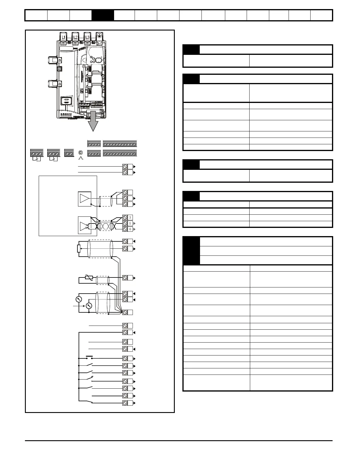
Figure 4-20 Default terminal functions
* Thermistor disabled by USA defaults.
4.14 General
4.14.1 Control terminal specification
Analog speed reference 1
Single-ended
signal
Differential signal
Reset
Run forward
Run reverse
Analog input 1/
input 2 select
8
Armature
current
Analog input 3
(Motor thermistor)
0V
Non-inverting input
Inverting input
0V
Non-inverting input
Inverting input
+10V output
Analog input 2
Analog input 3*
Analog output 1
Analog output 2
0V
0V
+24V output
0V
Digital I/O 1
Digital I/O 2
Digital I/O 3
Digital input 4
Digital input 5
Digital input 6
0V
Drive enable
Analog speed
reference 2
Polarized signal
connectors
Status
relay 1
Tac ho
41
42
51 52 53
Status
relay 2
61 62 63
1
21
11
31
A A\ B
B\
Z Z\ + 0
Encoder
+
_
Arm
current
MA1
MA2
1 0V common
Function
Common connection for all external
devices
2 +24V external input
Function
To supply the control circuit
without providing a supply to the
power stage
Nominal voltage +24.0Vdc
Minimum continuous operating
voltage
+19.2Vdc
Maximum continuous operating
voltage
+30.0Vdc
Minimum start-up voltage 21.6Vdc
Recommended power supply 60W 24Vdc nominal
Recommended fuse 3A, 50Vdc
3 0V common
Function
Common connection for all external
devices
4 +10V user output
Function Supply for external analog devices
Voltage tolerance ±1%
Nominal output current 10mA
Protection Current limit and trip @12mA
Precision reference analog input 1
5 Non-inverting input
6 Inverting input
Default function Speed reference
Type of input
Bipolar differential analog
(For single-ended use, connect terminal 6
to terminal 3)
Full scale voltage range ±10.0V ±1.5%
Absolute maximum
voltage range
+30V, -18V relative to 0V
Working common mode voltage
range
±16V
Input resistance
94k
Ω
Resolution 14-bit plus sign
Monotonic Yes
Dead band None
Jumps None
Maximum offset ±5mV
Maximum non linearity ±0.05% of Full scale voltage range
Maximum gain asymmetry ±0.2%
Input filter bandwidth single pole ~1kHz
Sampling period
250
μs if configured with the destination as
Pr 1.36, Pr 1.37, Pr 3.19 and Pr 4.08. 4ms
for all other destinations
 Loading...
