Safety
Information
Product
information
Mechanical
Installation
Electrical
installation
Getting
started
Basic
parameters
Running the
motor
Optimization
SMARTCARD
operation
Onboard
PLC
Advanced
parameters
Technical
data
Diagnostics
UL
information
Mentor MP User Guide 45
Issue: 3 www.controltechniques.com
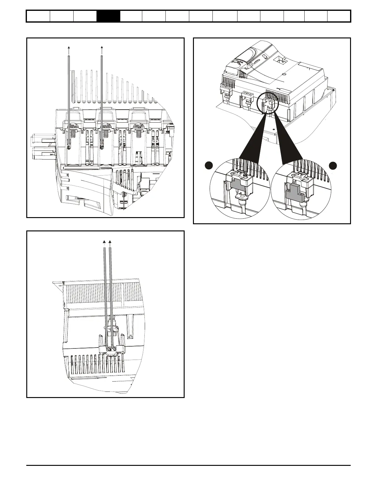
Figure 4-10 Location of external suppressor resistor terminals on
size 1 drives
Figure 4-11 Location of external suppressor resistor terminals on
size 2 drives
Figure 4-12 Removal of bucket suppressor terminals cover on
size 2C and 2D
1. Remove the 2 x M4 x 16 screws using a pozi drive screwdriver.
2. Remove the bucket suppressor terminal cover.
Shielded cable should be used for bucket suppressor connections. For
UL applications the cable should comply with UL1063 in accordance
with UL508a.
For applications where the external suppressor resistance is chosen to
be less than the recommended value for reasons of economy, it is
essential that the resistance is not less than the minimum resistance
shown in Table 4-19. However selecting a resistance less than the
recommended value requires a more complex installation. The power
rating of the resistor can be selected by the user according to the
dissipation required for the application, up to a maximum of the values
specified in Table 4-19.
To external suppression resistor
To external suppression resistor
 Loading...
