EasyManuals Logo
Home>Epson>Robotics>LS20 Series

Epson LS20 Series User Manual

Epson LS20 Series
176 pages
To Next Page IconTo Next Page
To Previous Page IconTo Previous Page
Page #102 background imageLoading...
Page #102 background image
Maintenance 5. Arm #1
90 LS20 Rev.4
5.2 Replacing Joint #1 Reduction Gear Unit
A reduction gear unit consists of the following three parts. When replacing the reduction
gear unit, be sure to always replace the waveform generator, flexspline, and circular spline
all together as one set.
Waveform generator, Flexspline, Circular spline
For details of the reduction gear unit, refer to Maintenance: 14. Maintenance Parts List.
Name
Quantity
Note
Maintenance
Parts
Reduction Gear Unit 1 1646483
Tools
Hexagonal wrench
width across flats: 2.5 mm
1
For M5 set screw
width across flats: 3 mm
1
For M4 screw
width across flats: 4 mm
1
For M5 screw
width across flats: 5 mm
1
For M6 set screw
width across flats: 6 mm
1
For M8 screw
Cross-point screwdriver (#2)
1
For M4 screw
Torque wrench
1
Nippers
1
Spatula
1
For apply grease
Wiping cloth
1
For wiping grease (Flange)
1
For wiping grease (Bolt)
Grease
Grease (SK-1A)
-
-
Joint #1
R
eduction
G
ear Unit
Removal
(1)
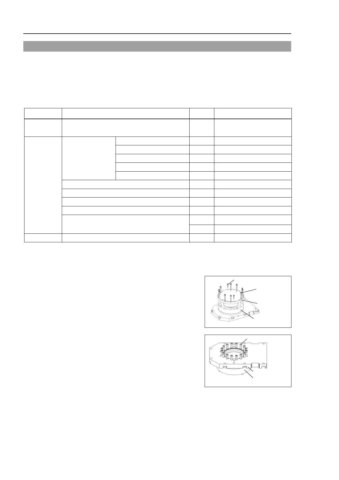
Remove the Joint #1 motor unit.
Follow
the removal steps in Maintenance: 5.1 Replacing Joint #1 Motor.
(2)
Remove the
spacer from the reduction gear
unit
.
8-M5×40
Spacer
Reduction
Gear Unit
4-M4
×15
(3)
Remove the
reduction gear unit from the Top
plate
.
16-M5×30
Top Plate
Reduction
Gear Unit

Table of Contents

Questions and Answers:

Question and Answer IconNeed help?

Do you have a question about the Epson LS20 Series and is the answer not in the manual?

Epson LS20 Series Specifications

General IconGeneral
BrandEpson
ModelLS20 Series
CategoryRobotics
LanguageEnglish

Related product manuals