Setup & Operation 5. Motion Range
LS20 Rev.4 51
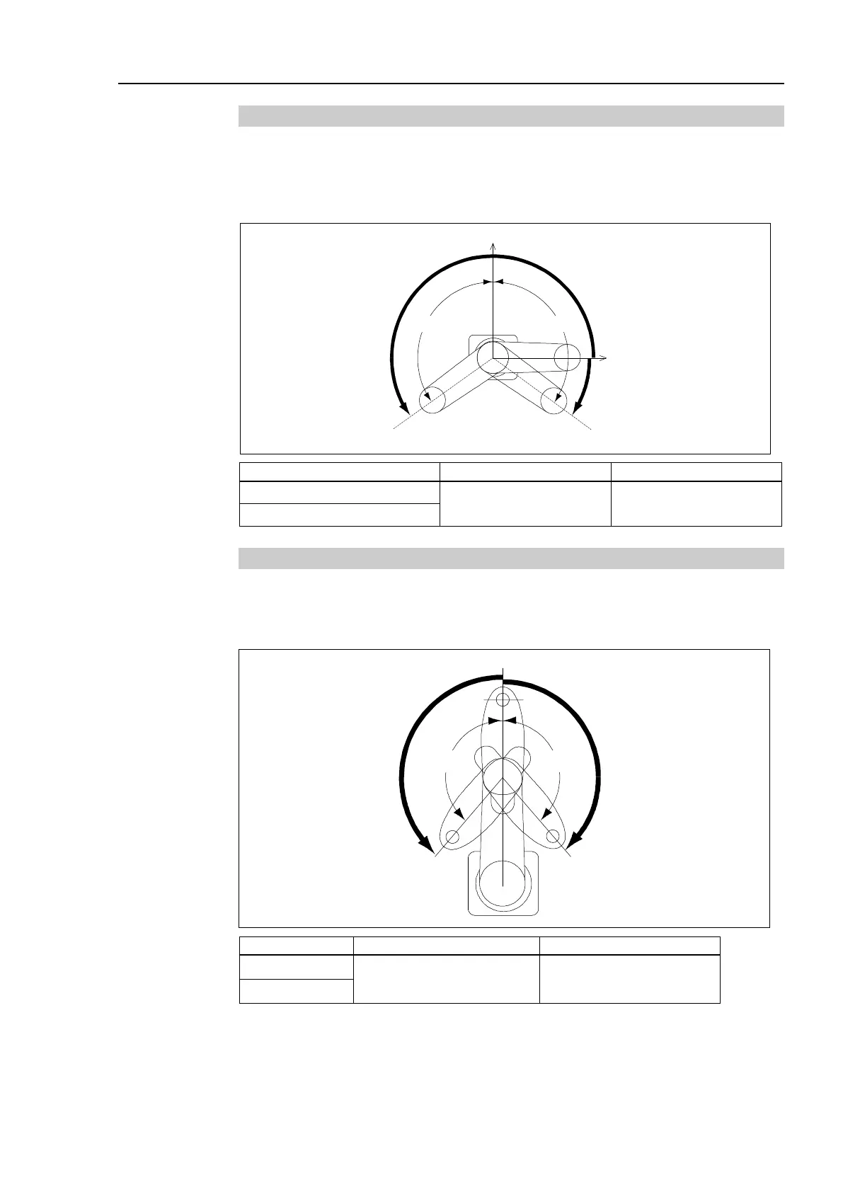
5.1.1 Max. Pulse Range of Joint #1
The 0 (zero) pulse position of Joint #1 is the position where Arm #1 faces toward the
positive (+) direction on the X-coordinate axis.
When the 0 pulse is a starting point, the counterclockwise pulse value is defined as the
positive (+) and the clockwise pulse value is defined as the negative (-).
LS20-804*
±132 deg.
- 152918 ~ 808278 pulse
LS20-A04*
5.1.2 Max. Pulse Range of Joint #2
The 0 (zero) pulse position of Joint #2 is the position where Arm #2 is in-line with Arm #1.
With the 0 pulse as a starting point, the counterclockwise pulse value is defined as the
positive (+) and the clockwise pulse value is defined as the negative (-).
LS20-804*
± 152 deg.
± 345885 pulse
LS20-A04*
 Loading...


