Maintenance 7. Arm #3
LS20 Rev.4 111
7.3 Replacing the Brake
Electromagnetic brake 1 1499588
Tools
Hexagonal wrench
width across flats: 1.5 mm
The brakes are mounted on the Joints #3 and #4 to prevent the shaft from moving down
due to the weight of the end effector while the power to the Controller is OFF or while the
motor is in OFF status (MOTOR OFF).
Move the shaft down to its lower limit before the replacement procedure following the
removal steps.
Joint #3 brake
Removal
Push down the shaft to its lower limit while pressing the brake release switch.
Be
sure to keep enough space and prevent the end effector hitting any peripheral
equipment.
The brake release switch is applied to both Joints #3 and Joint #4.
brake release switch is pressed, the respective brakes of the Joint #3
are released simultaneously. Be careful of the sh
aft falling and rotating while
the brake release switch is
being pressed because the shaft may be lowered by
the weight of an end effector.
Arm Top Cover.
For details, refer to Maintenance: 3.1 Arm Top Cover.
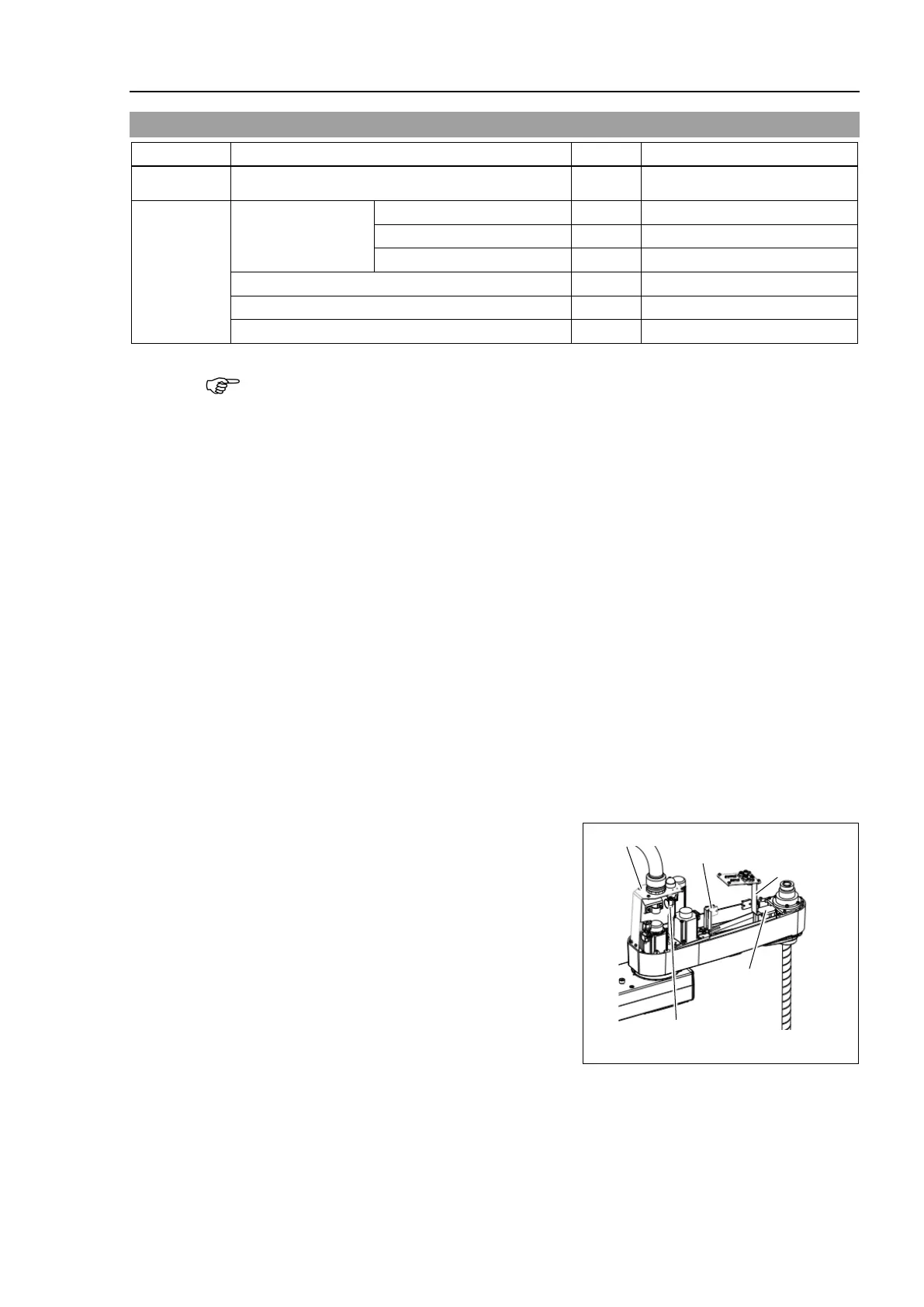
Remove the clip band binding the motor
cables.
Remove the wire tie on the cables fixed to
the belt tensioner.
At this point, do not cut off a wire tie that
binds the cables to the Duct Plate.
following connector.
Connector: X32
 Loading...


