Maintenance 10. Ball Screw Spline Unit
LS20 Rev.4 135
10.2 Replacing the Ball Screw Spline Unit
A brake is mounted on the motor of Joints #3 and #4 to prevent the shaft from moving
down due to the weight of the end effector while the power to the Controller is OFF or
while the motor is in OFF status (MOTOR OFF).
Move the shaft down to its lower limit before the replacement procedure following the
removal steps.
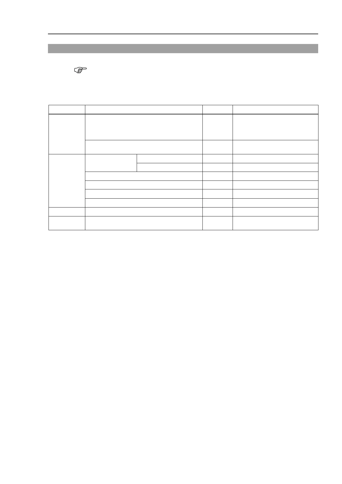
Maintenance
parts
Ball Screw Spline Unit 1
Each manipulator model
(Refer to Maintenance:
For Ball Screw Spline Unit (AFB grease)
6012557
Tools
Hexagonal wrench
Cross-point screwdriver (#2)
For wiping grease (Spline shaft)
Grease
For Ball Screw Spline Unit (AFB grease)
-
Screw
pline Unit
Push down the shaft to its lower limit while pressing the brake release switch. Be
sure to keep enough space and prevent
the end effector hitting any
The brake release switch is applied to both Joints #3 and Joint #4.
When the brake release switch is pressed, the respective brakes of the Joint #3 and
Joint #4 are
released simultaneously.
shaft falling and rotating while the brake release switch is
because the shaft may be lowered by the weight of an end effector.
Detach the wires/tubes from the
end effector, and remove the end effector.
tep is only for Cleanroom-model.
bellows. For details, refer to Maintenance: 9. Bellows.
Arm Top Cover and Arm Bottom Cover.
Maintenance: 3. Covers.
Joint #3 motor unit, Joint #4 motor unit
For details, refer to
Maintenance: 7.1 Replacing Joint #3 Motor s.
Maintenance:8.1 Replacing Joint #4 Motor s.
 Loading...


