Setup & Operation 5. Motion Range
50 LS20 Rev.4
5. Motion Range
CAUTION
■
When setting up the motion range for safety, both the pulse range and
mechanical stops must always be s
et at the same time.
The motion range is preset at the factory as explained in Setup & Operation: 5.4 Standard
Motion Range. That is the maximum motion range of the Manipulator.
There are three methods for setting the motion range described as follows:
1. Setting by pulse range (for all joints)
2. Setting by mechanical stops (for Joints #1 to #3)
3. Setting the Cartesian (rectangular) range in the X, Y coordinate system of the
Manipulator (for Joints #1 and #2)
Rectangular range setting
When the motion range is changed due to layout efficiency or safety, follow the
descriptions in 5.1 to 5.3 to set the range.
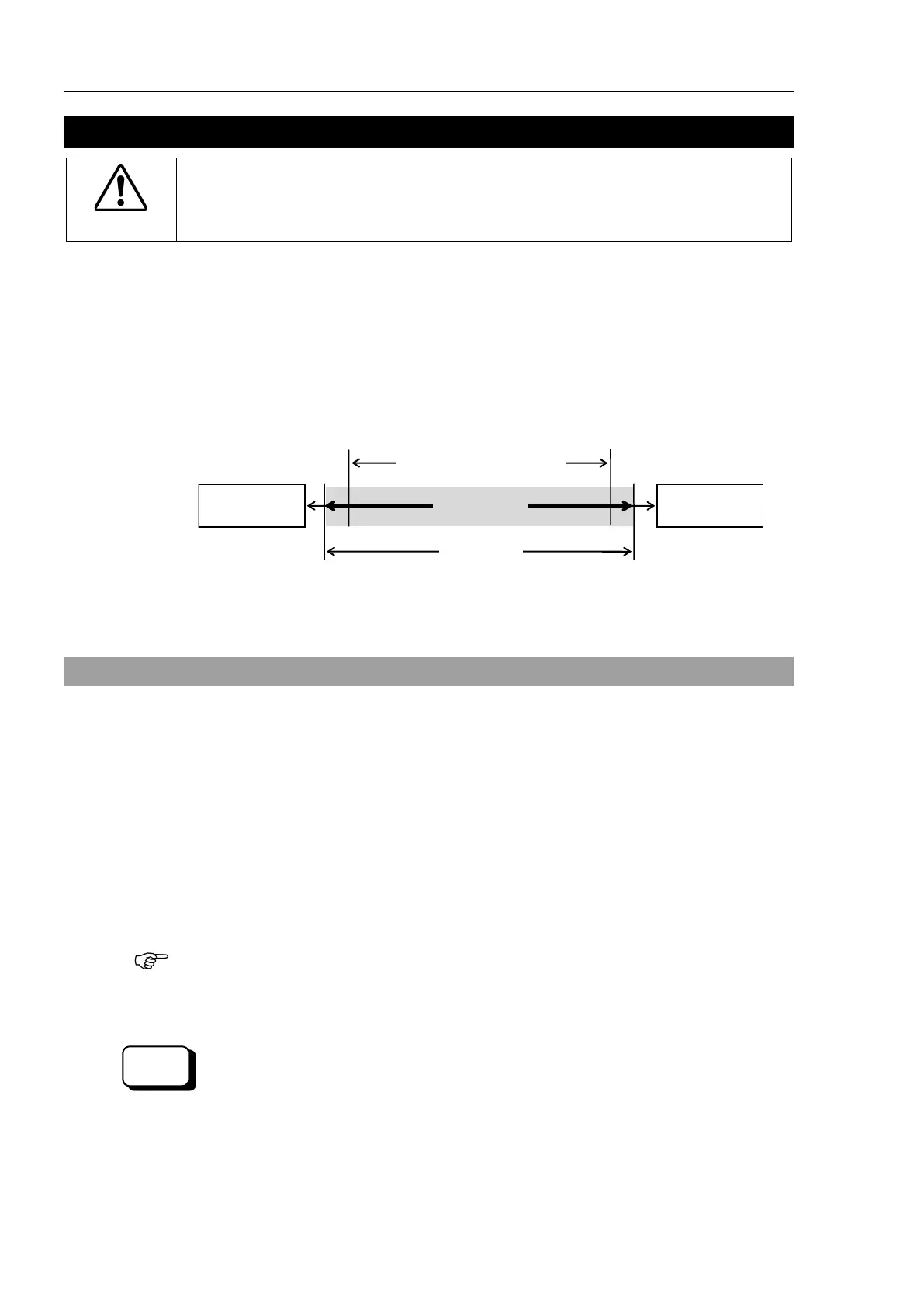
5.1 Motion Range Setting by Pulse Range (for All Joints)
Pulses are the basic unit of Manipulator motion. The motion range of the Manipulator is
controlled by the pulse range between the pulse lower limit and upper limit of each joint.
Pulse values are read from the encoder output of the servo motor.
For the maximum pulse range, refer to the following sections.
The pulse range must be set inside of the mechanical stop range.
5.1.1 Max. Pulse Range of Joint #1
5.1.2 Max. Pulse Range of Joint #2
5.1.3 Max. Pulse Range of Joint #3
5.1.4 Max. Pulse Range of Joint #4.
Once the Manipulator receives an operating command, it checks whether the target
position specified by the command is within the pulse range before operating. If the
target position is out of the set pulse range, an error occurs and the Manipulator does not
move.
e range can be set on the [Range] panel shown by selecting [Tools]-[Robot
Manager]. (You may also execute the Range command from the [Command Window].)
EPSON
 Loading...


