EasyManuals Logo
Home>Epson>Robotics>LS20 Series

Epson LS20 Series User Manual

Epson LS20 Series
176 pages
To Next Page IconTo Next Page
To Previous Page IconTo Previous Page
Page #171 background imageLoading...
Page #171 background image
Maintenance 13. Calibration
LS20 Rev.4 159
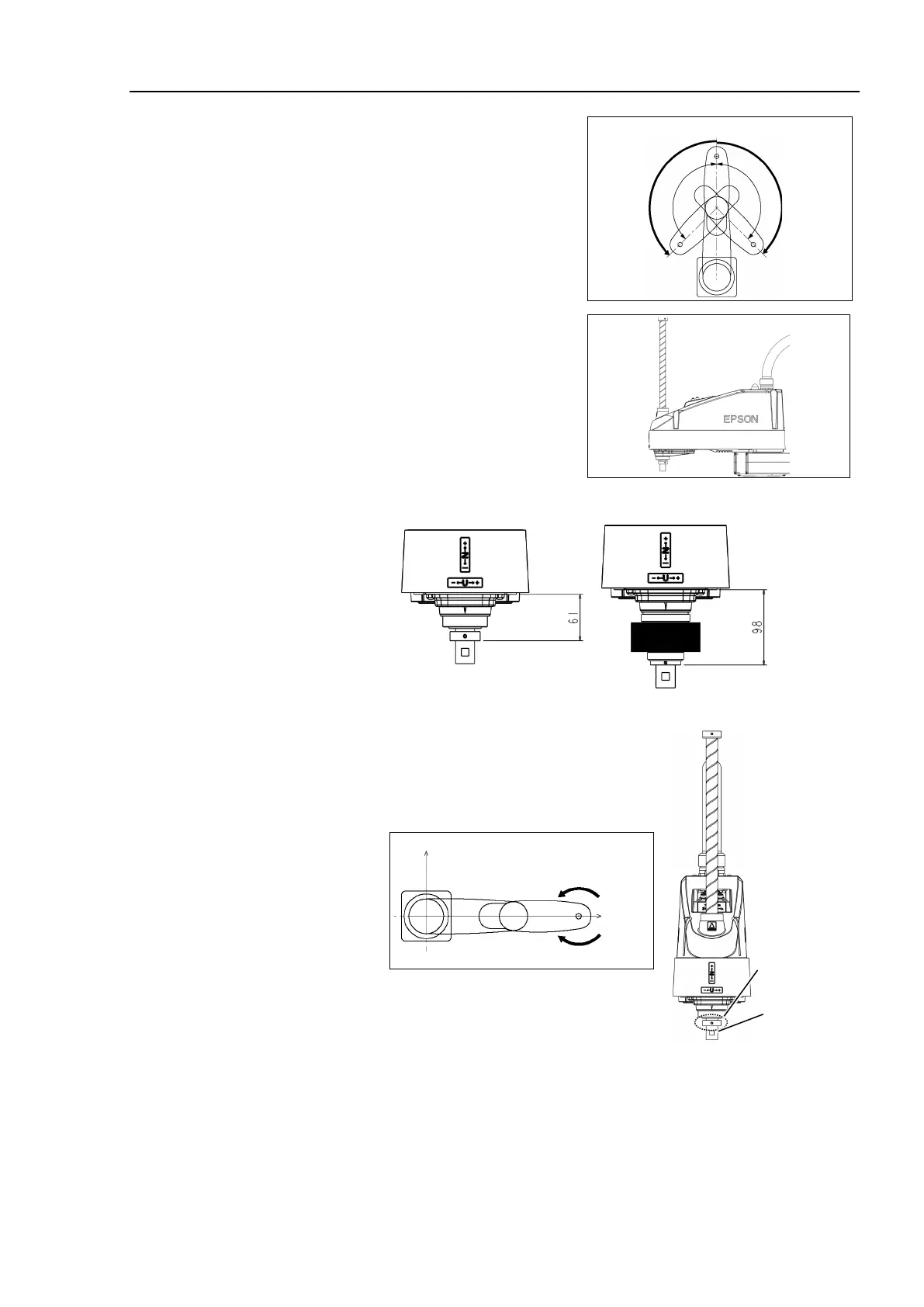
0 pulse position of Joint #2:
position where Arms #1 and #2
are in a straight line
(Regardless of the Joint #1
direction.)
0 pulse
+
0 pulse position of Joint #3:
upper limit position in motion
range
The height of Joint #3 depends on manipulator model.
LS20-804S, LS20-A04S
LS20-804C, LS20-A04C
0 pulse position of Joint #4:
position where the flat surface of the shaft (or
the set screw of the bottom mechanical stop)
faces toward the tip of Arm #2.
0 pulse
+
Set Screws
Flat Surface
(3)
-3 Connect EPSON RC+ to the Controller.
Select a robot to be calibrated. Input as below in the [Command Window] and
execute it.
(This example uses “robot 1”.)
> robot 1

Table of Contents

Questions and Answers:

Question and Answer IconNeed help?

Do you have a question about the Epson LS20 Series and is the answer not in the manual?

Epson LS20 Series Specifications

General IconGeneral
BrandEpson
ModelLS20 Series
CategoryRobotics
LanguageEnglish

Related product manuals