EasyManuals Logo
Home>Epson>Robotics>LS3-401 series

Epson LS3-401 series User Manual

Epson LS3-401 series
186 pages
To Next Page IconTo Next Page
To Previous Page IconTo Previous Page
Page #106 background imageLoading...
Page #106 background image
Maintenance 5. Arm #1
92 LS Rev.10
5.1 Replacing Joint #1 Motor
Name Quantity Note
Maintenance
parts
AC Servo Motor (200 W) 1 R13B000102
Tools
Hexagonal wrench
width across flats: 2 mm
1
For M4 set screw
width across flats: 3 mm
1
For M4 screw
Torque wrench
1
Wiping cloth
1
For wiping grease
Grease
Grease (SK-1A)
-
-
Joint #1 motor
Removal
(1)
Remove the
Connector Plate.
For details, refer to
Maintenance: 3.3 Connector Plate.
(2)
Disconnect the
connector X111. (Hold the claw to remove.)
(3)
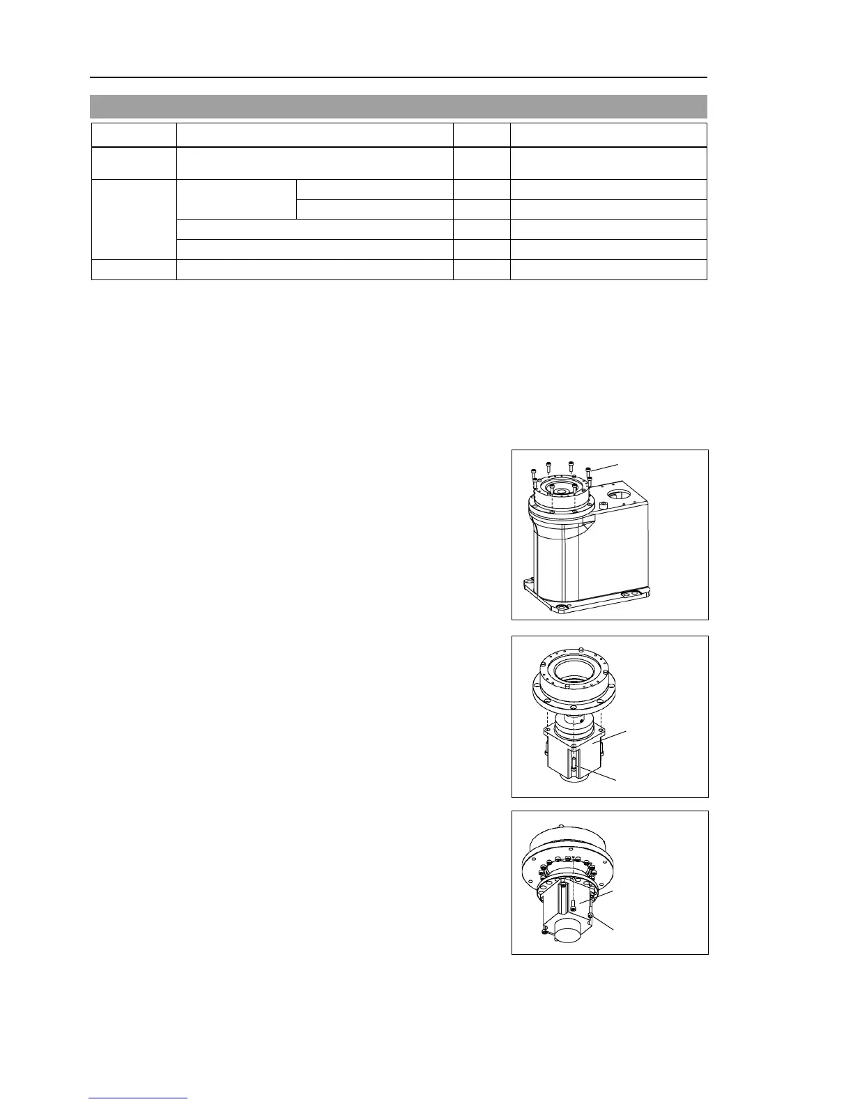
Remove the Arm #1 mounting bolt in the Joint #1 side and remove
the arm.
There is an O
-ring between the Joint #1 unit and the arm. Be sure to keep the O-ring.
(4)
Remove the screw
s mounting the Joint #1 flange
on the B
ase.
LS3: 8-M4×12
LS6: 6
-M5×15
(5)
Hold
up the Joint #1 unit and remove the
connector X10 from the resolver board.
(6)
LS3:
Loosen the motor mounting
screws on the
Joint #1
motor flange and remove the
motor unit
There is a
n O-ring in the assembly
position of the motor
and Joint #1 flange.
Be sure to keep the
O-ring.
4-M4×15
Joint #1
Motor Unit
LS6:
Loosen the motor
flange mounting screws
on the
Joint #1 motor flange and remove
the motor unit
There is a
n O-ring in the assembly
position of the motor
and Joint #1 flange.
Be sure to keep the
O-ring.
4-M4×12
Joint #1
Motor Unit

Table of Contents

Questions and Answers:

Question and Answer IconNeed help?

Do you have a question about the Epson LS3-401 series and is the answer not in the manual?

Epson LS3-401 series Specifications

General IconGeneral
BrandEpson
ModelLS3-401 series
CategoryRobotics
LanguageEnglish

Related product manuals