Maintenance 8. Arm #4
122 LS Rev.10
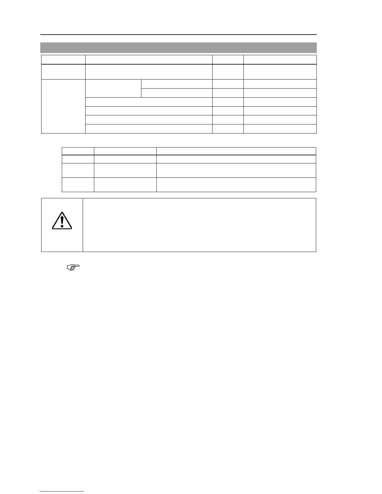
8.1 Replacing Joint #4 Motor
AC Servo Motor (100 W) 1 R13B000101
Tools
Hexagonal wrench
Suitable cord (Length about 800 mm)
* : Regarding U axis belt setting tension
LS6 (a)
39N (4.0 ± 0.5 kgf)
S/N: L6**00****,
or Controller firmware Ver. 7.1.4.3 or earlier
LS6 (b)
58N (5.9 ± 0.5 kgf)
S/N: L6**01**** or later,
and Controller firmware Ver. 7.1.6.0 or later
The belt must be installed with proper tension;
otherwise the following problems
If falling below the lower limit : Jumping of the belt gears (position gap)
If exceeding the upper limit : Abnormal noise or vibration (oscillation),
decline in the life of driving parts
LS3: A brake is mounted on the Joint #3 motor to prevent the shaft from lowering down
due to the weight of the end effector while the power to the Controller is OFF or
while the motor is in OFF status (MOTOR OFF).
LS6: A brake is mounted on the motor of Joints #3 and #4 to prevent the shaft from
moving down due to the weight of the end effector while the power to the Controller
is OFF or while the motor is in OFF status (MOTOR OFF).
Move the shaft down to its lower limit before the replacement procedure following the
removal steps.
Push down the shaft to its lower limit while pressing the brake release switch. Be
sure to keep enough space and prevent
the end effector hitting any
The brake release switch affects only Joint #3. When the brake release switch
is pressed, the Joint #3 brake is released.
Be careful of the shaft while the brake release switch is being pressed
the shaft may be lowered by the weight of an end effector.
The brake release switch is applied to both Joints #3 and Joint #4.
When the brake release switch is pressed, the respective brakes of the Joint #3
and Joint #4 are released simultaneously.
Be careful of the shaft falling and rotating while the brake release switch is
pressed because the shaft may be lowered by the weight of an end effector.
 Loading...


