Maintenance 10. Ball Screw Spline Unit
LS Rev.10 143
10.2 Replacing the Ball Screw Spline Unit
LS3: A brake is mounted on the Joint #3 motor to prevent the shaft from lowering down
due to the weight of the end effector while the power to the Controller is OFF or
while the motor is in OFF status (MOTOR OFF).
LS6: A brake is mounted on the motor of Joints #3 and #4 to prevent the shaft from
moving down due to the weight of the end effector while the power to the Controller
is OFF or while the motor is in OFF status (MOTOR OFF).
Move the shaft down to its lower limit before the replacement procedure following the
removal steps.
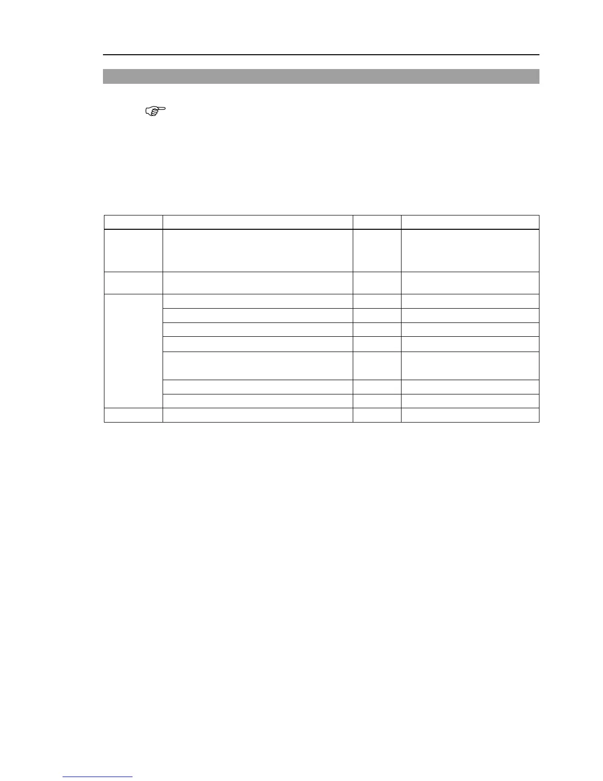
Maintenance
parts
Ball Screw Spline Unit 1
Each manipulator model
(Refer to Maintenance:
Grease
For Ball Screw Spline Unit (AFB grease)
Hexagonal wrench (width across flats: 3 mm)
Force gauge
1 Belt tension
98 N (10 kgf) / 74 N (7.5 kgf)
Suitable cord (Length about 1000 mm)
For wiping grease (Spline shaft)
Push down the shaft to its lower limit while pressing the brake release switch. Be
sure to keep enough space and prevent
the end effector hitting any
The brake release switch affects only Joint #3. When the brake release switch
is pressed, the Joint #3 brake is released.
Be careful of the shaft while the brake release switch is being pressed
the shaft may be lowered by the weight of an end effector.
The brake release switch is applied to both Joints #3 and Joint #4.
When the brake release switch is pressed, the respective brakes of the Joint #3
and Joint #4 are released simultaneously.
Be careful of the shaft falling and rotating while the brake release switch
being pressed because the shaft may be lowered by the weight of an end effector
wires/tubes from the end effector, and remove the end effector.
tep is only for Cleanroom-model.
bellows. For details, refer to Maintenance: 9. Bellows.
 Loading...


