SC-F2000 Revision C
DISASSEMBLY & ASSEMBLY Disassembly and Assembly Procedure 185
Confidential
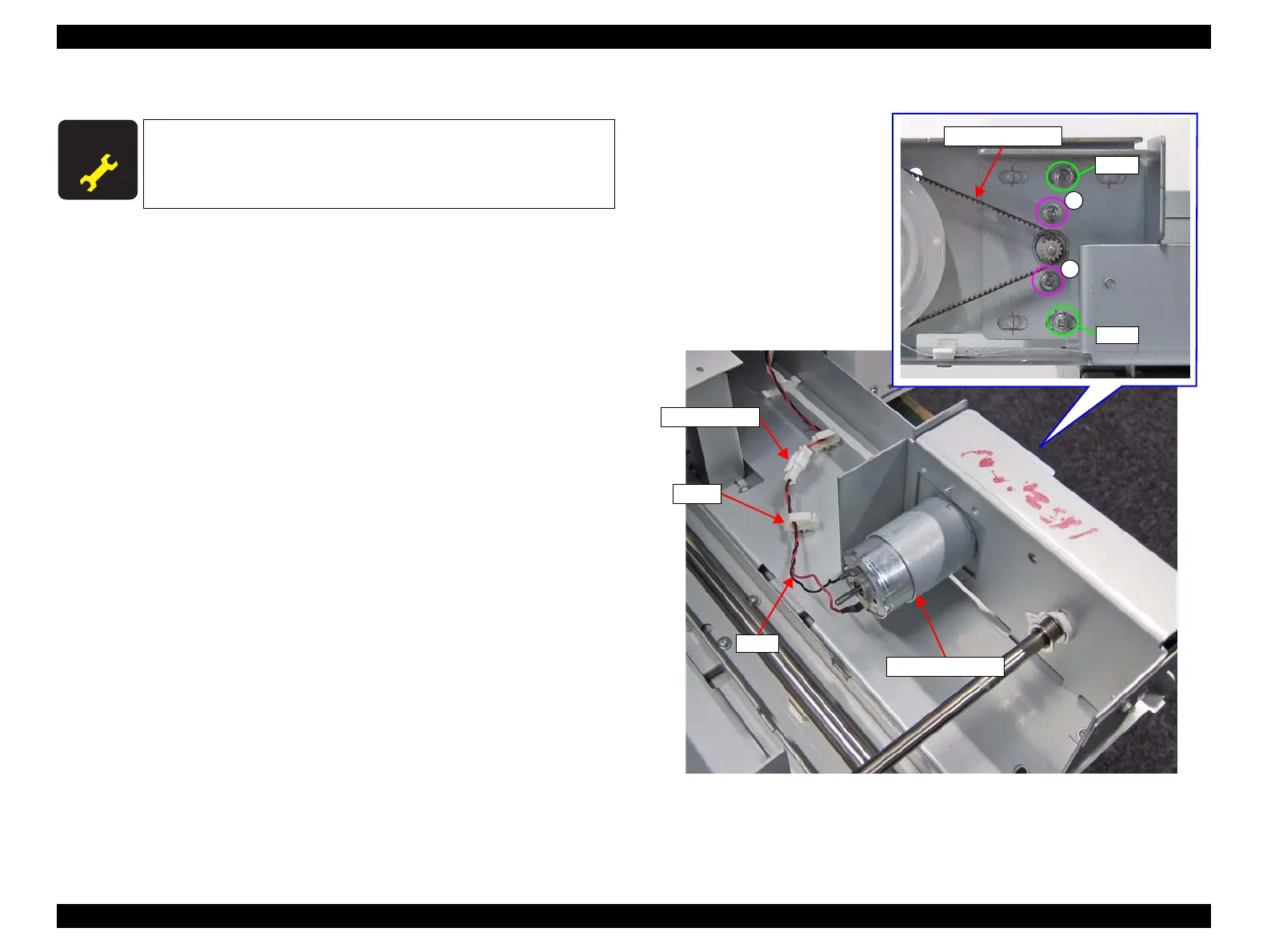
3.4.6.12 TF MOTOR ASSY
1. Remove the REAR COVER SUB ASSY. (p77)
2. Remove the Rear Bottom Sub Frame. (p183)
3. Loosen the two screws, and loosen the tension of the TF TIMING BELT.
4. Remove the two screws, and remove the TF MOTOR ASSY.
A) Silver M3x5 machine screw: 2 pcs
5. Release the cable from the clamp.
6. Disconnect the cable from the relay connector.
Figure 3-151. Removing the TF MOTOR ASSY
A D J U S T M E N T
R E Q U I R E D
When replacing this part, refer to “4.1.2 Adjustment Items and
the Order by Repaired Part” (p194) and make sure to perform the
specified operations including required adjustment.
A
A
Screw
TF TIMING BELT
Screw
Relay connector
TF MOTOR ASSY
Cable
Clamp
TF MOTOR ASSY
 Loading...