19
E1SL 28 532258 04 - Rev. B
TX2
RX2
TX1
RX1
T1 G
T2
R1
G R2
+ RX2
GND
+ RX1
+ TX2
GND
+ TX1
J9
TX1
RX1
T1 G
T2
R1
G R2
+ R2
GND
+ R1
+ T2
GND
+ T1
J9
Translation of the original instructions
ENGLISH
blueblue
blue
blue
blue
blue
blackblack
black
grey
grey
grey
black
black
black
grey
grey
grey
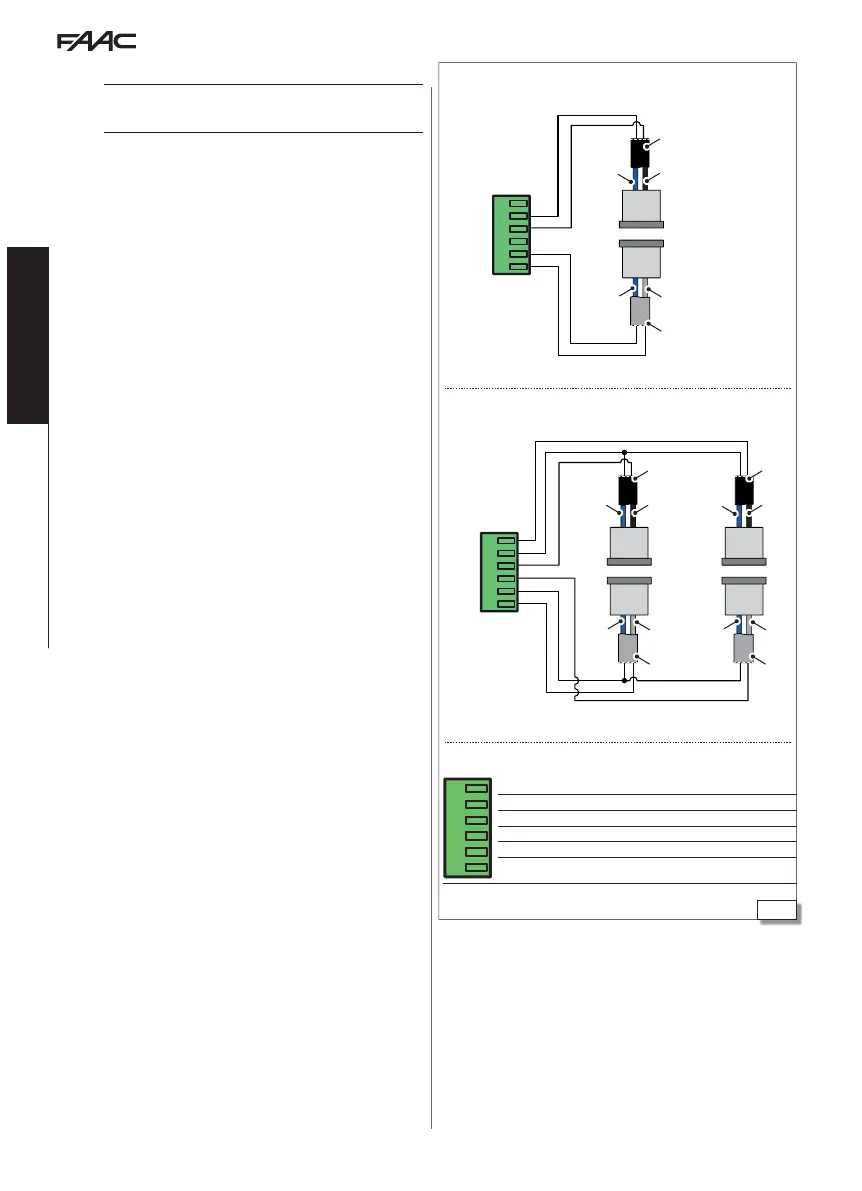
2 Pairs of button photocells connection
1 Pair of button photocells connection
XFA BUTTON PHOTOCELLS
!
Photocells are not permitted as safety devices in European Community
countries in which the EN 16005:2012 standard is in force. Specifically,
photocells are considered as auxiliary devices, complementary to safety.
Button photocells are monitored by the electronic board, which
controls correct operation at each movement.
1. Connect the photocells.
CABLE colour
TX - transmitter grey and blue (grey sheath)
RX - receiver black and blue (black sheath)
Note: leave the inputs of the connector free if button photocells are
not used.
2. Enable the photocells.
- from Board: advanced programming
bP = 1 1 pair
bP = 2 2 pairs
or
- from SDK EVO:
/
PROGRAMMING/INPUTS OUTPUTS/PHOTOCELLS XFA 1 PAIR or 2 PAIRS
J9
T1 G
T2
R1
G R2
R2 2nd pair receiver connection
G GND Receiver negative
R1 1st pair receiver connection
T2 2nd pair transmitter connection
G GND Transmitter negative
T1 1st pair transmitter connection

 Loading...