3
4
E1SL 5 532258 04 - Rev. B
0.0
RESET/SETUP
DL2
DL11
MAIN
F1
USB
+
-
F
ERR
BAT1
OPEN
EMERG
BAT2
SIC
_
OP
SIC
_
CL
J10
J14
J11
J12
J13
V G
S1
G
T
J
J17
V RX TX G
J8
E1 G E2
J7
T1 G
T2
R1
G R2
J9
V G 01 02 02
J22
J21
V
G
I1
I2
G
I3
I4
V
J18
G CH CL G
J23J24
J25
V G
S2
G
T
J4
J24
J25
J22
J18
J7
J4
J1
J9
J23
J17
J13
J12
J11
J14
J10
J21
J8
0.0
RESET/SETUP
DL2
DL11
MAIN
F1
USB
+
-
F
ERR
BAT1
OPEN
EMERG
BAT2
SIC
_
OP
SIC
_
CL
J10
J14
J11
J12
J13
V G
S1
G
T
J
J17
V RX TX G
J8
E1 G E2
J7
T1 G
T2
R1
G R2
J9
V G 01 02 02
J22
J21
V
G
I1
I2
G
I3
I4
V
J18
G CH CL G
J23J24
J25
V G
S2
G
T
J4
USB
BAT2
SIC_CL
OPEN
SIC_OP
EMERG
DL2
BAT1
MAIN
ERR
DL11
Translation of the original instructions
ENGLISH
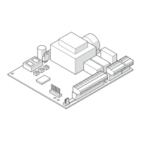
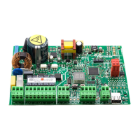
LED Description
MAIN BLUE main power supply unit input
DL2 BLUE board power +5V
DL11 BLUE accessories power (+24 V
"
)
USB GREEN USB storage device
ERR RED error or warning
BAT1 RED battery status
BAT2 GREEN battery charger status
SIC_OP RED safety in opening
SIC_OP and SIC_CL lit simultaneously = safety STOP
SIC_CL RED safety in closing
EMERG GREEN emergency command
OPEN GREEN OPEN command
STATUS LEDS ON THE BOARD
J1 Removable terminal board configurable inputs S1
J4 Removable terminal board configurable inputs S2
J7 Removable terminal board configurable inputs E1, E2
J8 Removable terminal board keypad or EVO functions selector
J9 Removable terminal board for button photocells
J10 Connector for main power supply 36 V, 4 A
J11 Connector for motor M1
J12 Connector for motor M1 encoder
J13 Connector for motor block and monitoring
J14 Connector for emergency battery
J17 USB port
J18 Removable terminal board INTERCOM
J21 Removable terminal board configurable inputs I1, I2, I3, I4
J22 Removable terminal board configurable outputs O1, O2
J23
J24
J25
Connectors for optional modules NOT USED
TERMINAL BOARDS AND CONNECTORS

 Loading...