32
31
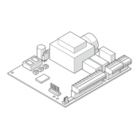
E1SL 42 532258 04 - Rev. B
V RX TX G
J8
J1
KS EVO
E1SL / E1RD
V RX TX G
V
VRX
RX
TX
TX
G
G
U/UTP CAT.5
4x2xAWG24
Translation of the original instructions
ENGLISH
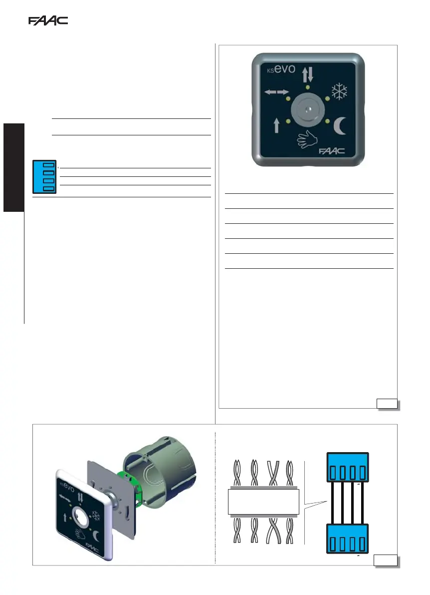
KS EVO allows you to select the operating mode by turning the key
to the corresponding icon.
INSTALLATION AND CONNECTION
1. Separate the parts (use a flat screwdriver to prise them apart).
2. Break the cable knockout.
3. Mark the points on the wall and fasten the support using suitable
screws.
F
Before connecting the device, disconnect the mains power supply and
the emergency battery of the automation system (if present).
4. Connect the automation board:
J8
V RX TX G
G GND Accessories power supply negative and Common contacts
TX Data transmission
RX Data reception
V +24 V
"
(accessories power supply)
- use a 4 twisted pair U/UTP AWG24 cable with a maximum length
of 50 m
5. Assemble the parts and fix it in place with the screws provided.
SWITCHING ON
Turn power to the automation board on.
- The LEDs turn on and off in sequence, then the LED correspond-
ing to the active operating mode remains on (apart from manual
mode).
ERROR WARNINGS In the event of errors, the combination of LEDs
corresponding to the active error flashes for a few seconds ( LED
Error Codes).
Total two-direction automatic
Door open
Automatic total one-direction
Automatic partial two-direction
Night
Manual
If the
LEDs are both lit at the same time, it indicates that
the automation is in an operating mode that is NOT available
on the KS EVO.
13. KS EVO
Assembling the KS EVO KS EVO connection Connect to the terminals as shown.

 Loading...