OptiView
TM
Series III
Getting Started Guide
22
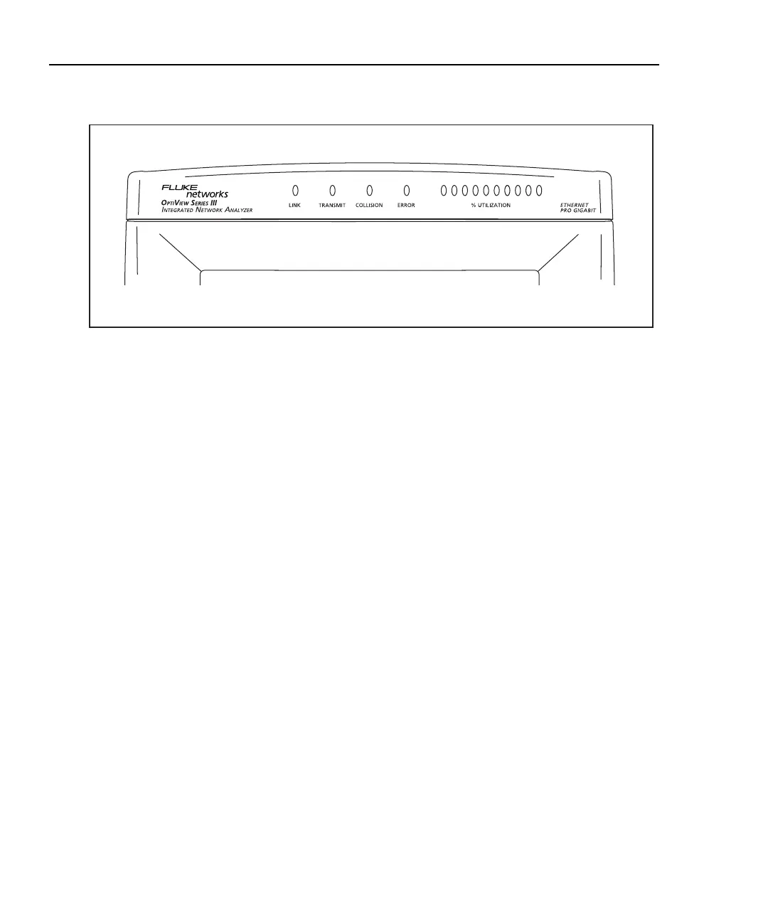
LED Status
xx
aww15f.eps
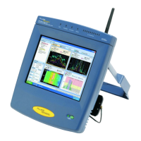
Figure 13. Analyzer Status LEDs
The LEDs on the front of the analyzer represent the following conditions:
Link – Green indicates link present.
Transmit - Indicates the analyzer is transmitting packets. Packets are transmitted
while running Traffic Generator, and routinely transmitted by the analyzer
discovery process. The analyzer communicates with devices to determine their
device type and identity. The LED will flash faster as more transmit activity from
the analyzer occurs.
Collision - Indicates that collisions have been detected by the analyzer on the local
network. As more collisions occur, the LED flashes faster.
Errors - Indicates that errors have been detected on the local network. Errors
include CRC alignment errors, undersized packets, oversized packets, and jabbers.
Utilization - Represents traffic at the point where the analyzer is connected (local
traffic). Ten LEDs indicate utilization in 10 percent increments. The first five
LEDs (from left-to-right) are green, followed by three amber LEDs (indicating
more traffic), then two red LEDs (indicating very heavy traffic).
 Loading...