TGA300 Rev180405
11
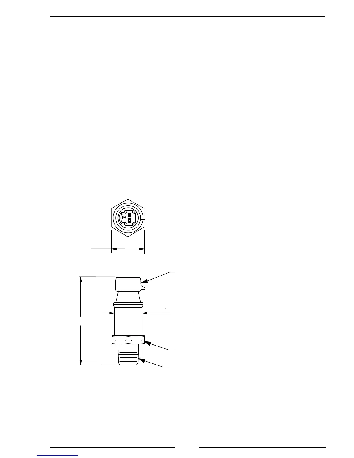
Figure 3. Pressure Sensor Dimensions
Install Pressure Sensors
Two pressure sensors are mounted on the pump manifolds, one on the discharge
and one on the intake. If there is a check valve in the discharge side of the pump,
mount the discharge sensor before the check valve. T-ttings can be used to mount
the pressure sensors.
Note: Install the pressure sensor upright so that water in the end of the pressure
sensor is able to drain back into the pipe.
1. Screw the sensor into a 1/4-18 NPT hole.
Caution: Do not use the main body that houses the electronics to tighten the
pressure sensor. Damage to the sensor may occur.
2. Tighten the sensor with a 7/8 inch wrench on the lower hex tting.
3. Connect the pressure sensor cable from the control module to the pressure
sensor. (Refer to Wiring Section.)
Caution: Do not use the main
body that houses the electronics
to tighten the sensor. Damage to
the sensor may occur.
Caution: The discharge and intake
pressure sensors are the same size.
Ensure the correct sensor is installed on
the correct manifold. Refer to Table 1.
1/4-18 NPT
7/8" Hex
0.75 [18.95]
2.37 [60.30]
Inch [mm]
Packard
Metri Pack
Connector
0.87 [22.05]
Across Flats
 Loading...