TGA300 Rev180405
44
J1939 CAN Bus Control
U
V
J1939 (–)
J1939 (+)
Pin 9 Black Wire
Pin 10 Red Wire
12-Pin
Connector
(Refer to
Figure 4)
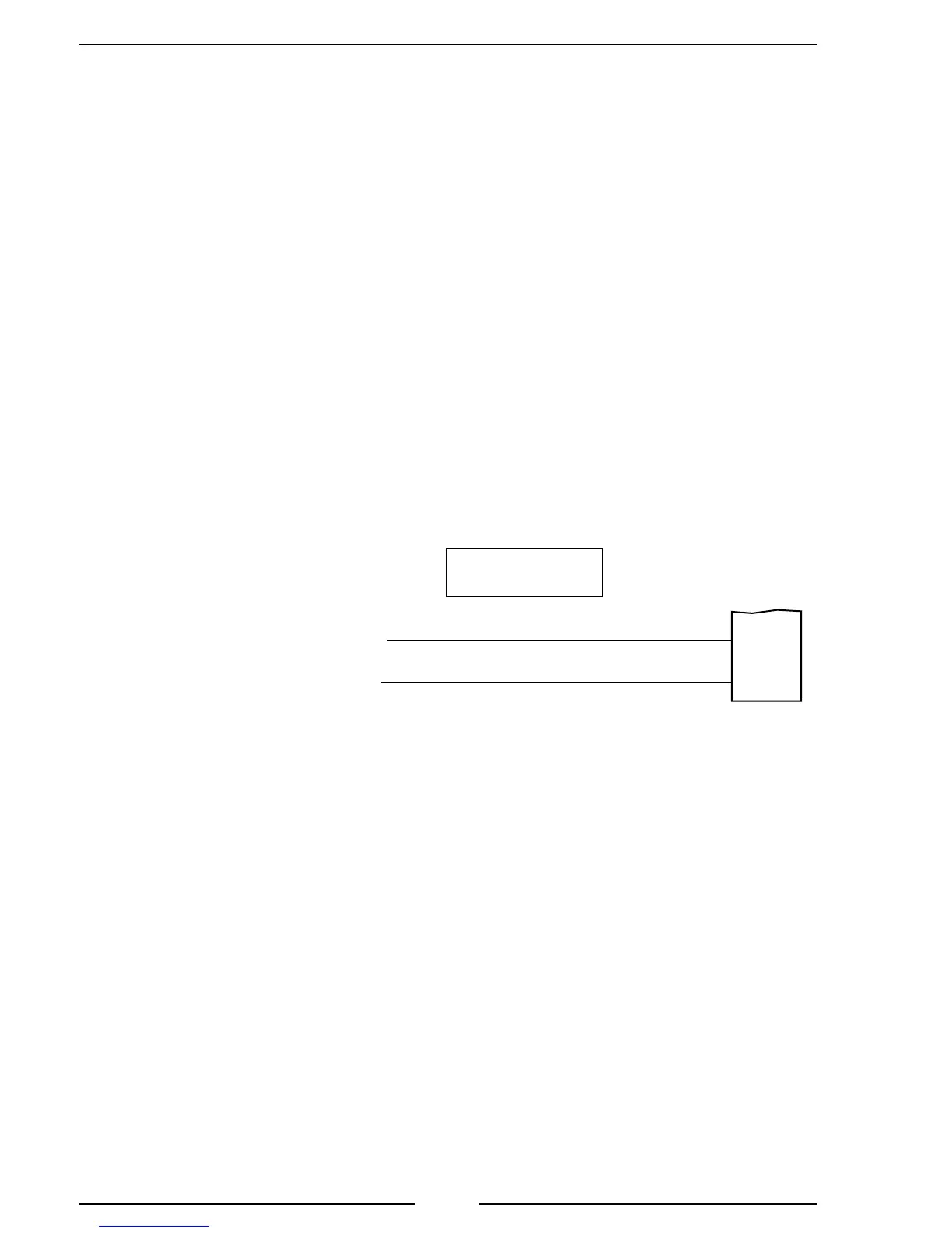
Figure 19. John Deere TGA316/416 Wiring
John Deere Harness Connections
Interface Information
CAN Controller will request a torque by means of TSC1. This option is disabled by
default and is selectable in the Trim Options page for this application. Source address
57 should be programmed.
Note: Refer to Figure 4. TGA 12-Pin Connector
Wiring for power and interlock wire connections.
Circuit No. 905 Green
Circuit No. 904 Yellow
21 Pin Deutsch
Connector
TIER-3
PowerTech Engines
 Loading...