TGA300 Rev180405
35
Caterpillar Harness Connections
Interface Information
The parameter settings for PTO Coguration is programmed to Remote Throttle
or Remote Throttle with J1939 Speed Command.
ECM software with a Personality Module release date of May08 for C7, C9,
C13, C15 engines, will have the Remote Throttle with J1939 Speed Command setting
available. This setting allows the engine speed to be controlled during PTO operations
by a J1939 compliant device.
Refer to an authorized dealer to program one of these options.
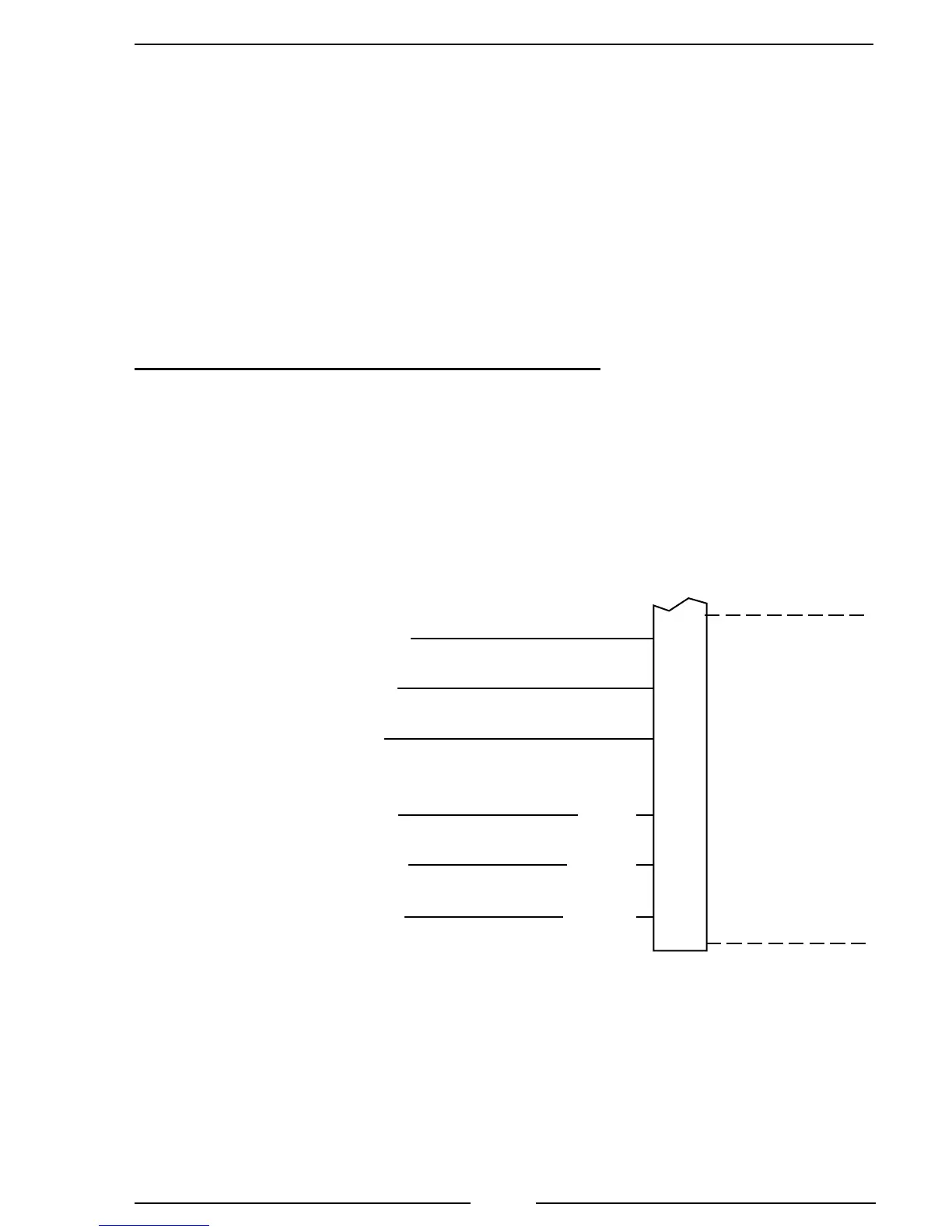
C7, C9, C10, C11, C12, C13, C15 Engine Interface
Engines with 70-pin OEM connector.
Figure 12. Caterpillar TGA305/405 Wiring
Note: Refer to Figure 4. TGA 12-Pin Connector Wiring
for power and interlock wire connections.
12-Pin
Connector
(Refer to
Figure 4)
8-Pin
Connector
(Refer to
Figure 5)
J1939 Datalink
Negative (–)
J1939 Datalink Shield
J1939 Datalink
Positive (+)
K999-GN
993-BR
G845-PU
Input Sensor
Common #2
Input #1 PTO ON/OFF
Switch
Input #8 (Remote
Throttle PWM)
ECM
70-Pin Vehicle
Harness Connector
3
68
56
34
42
50
Pin 2 Black Wire
Pin 3 Orange Wire
Pin 8 Brown Wire
Pin 12 Yellow Wire
Pin 5 Black Wire
Pin 4 Red Wire
K900-YL
K990-GN
A249-BK
 Loading...