TGA300 Rev180405
43
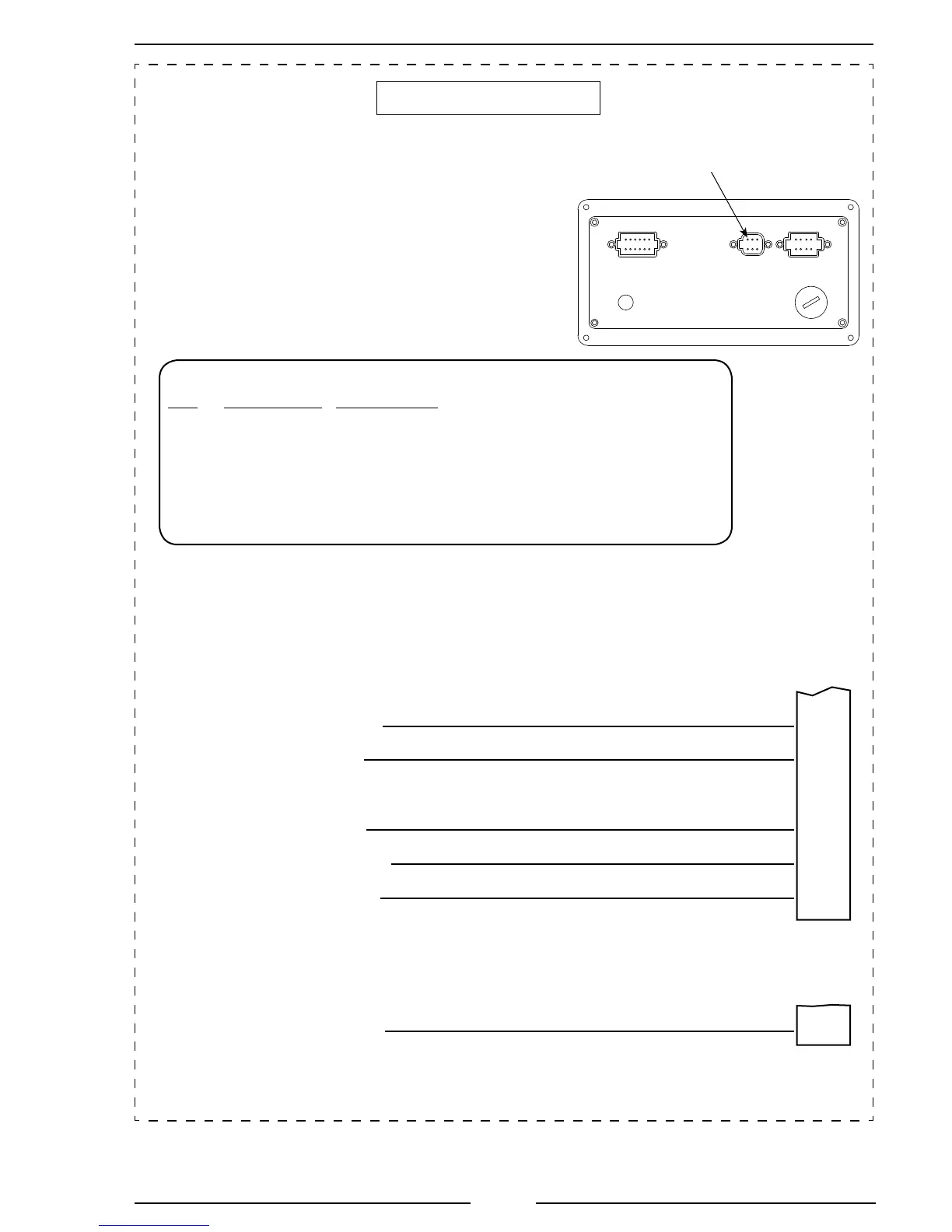
Figure 18. Mercedes TGA310/410 Wiring
Sheet 2 of 2
ACTROS Wiring
X 3
15-Pin
Connector
X 1
18-Pin
Connector
18/10
18/11
Remote Throttle Signal Analog
Remote PTO Power Supply
18/12
Sensor Ground (Throttle Pedal & Remote)
15/4
Remote Throttle Enable
J1939 (–)
18/18
18/16
J1939 (+)
12-Pin
Connector
(Refer to
Figure 4)
8-Pin
Connector
(Refer to
Figure 5)
Pin 1 Red Wire
Pin 3 Orange Wire
Pin 2 Black Wire
Pin 8 Brown Wire
Pin 5 Black Wire
Pin 4 Red Wire
Pin 1
Note: The optional 6-Pin Connector is for inputs that are not available on J1939
6-Pin Optional Connector/Cable
Pin Wire Color Description
1 Blue RPM Signal (TTL or Alternator Pulse Input)
2 Orange Oil Sensor Signal
3 Red Engine Coolant Temp Sensor Signal
4 Black Transmission Temp Sensor Signal
5 White Foot Pedal Signal Input
6 Green Check Engine LED Input
 Loading...