TGA300 Rev180405
38
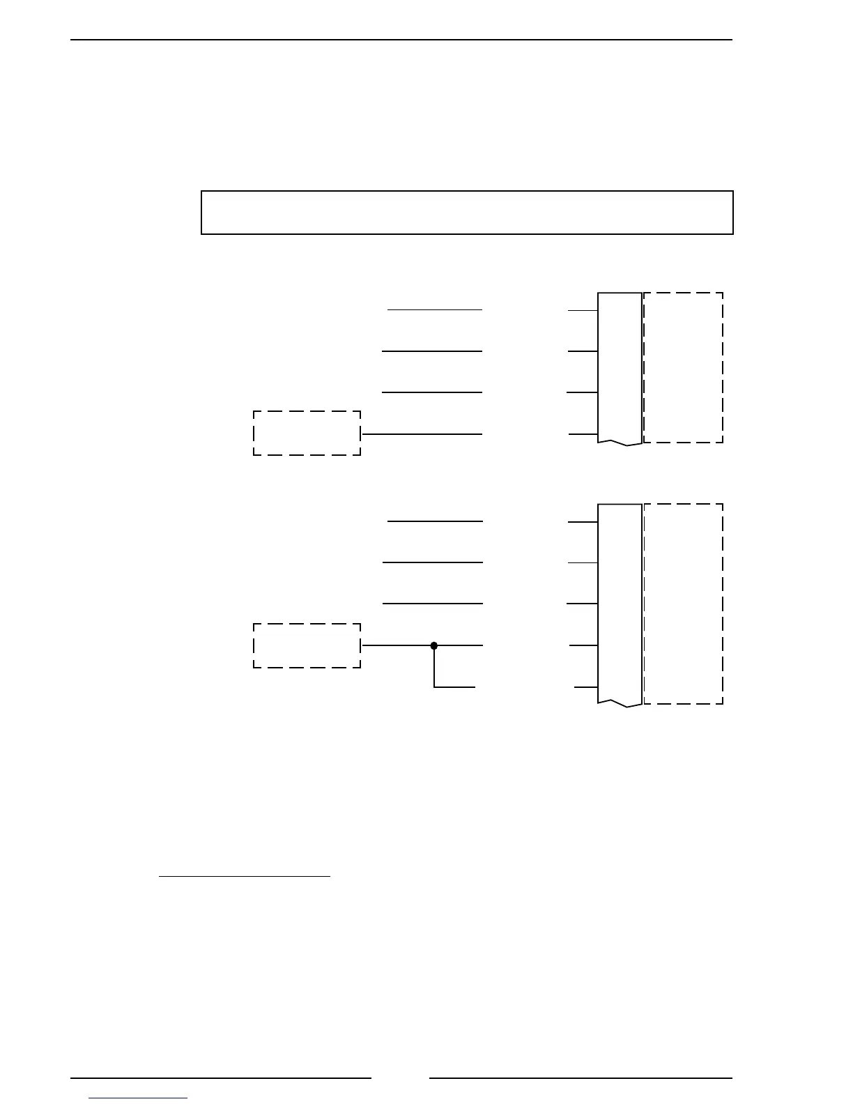
Figure 14. Ford TGA306/406 PCM Wiring
2011 Model F-250/350/450/550 - 6.7L Diesel Engine
Stationary Elevated Idle Control (SEIC)
Note: Do not press the accelerator or service brake pedal when engaging the
re pump, this prevents the switch into SEIC.
Access wires for SEIC are located in cabin, tagged and bundled
above the parking brake pedal assembly behind datalink connector.
Note: Refer to Figure 4. TGA 12-Pin Connector Wiring
for power and interlock wire connections.
8-Pin
Connector
(Refer to
Figure 5)
PCM
PTO REF
PTO RTN
PTO RPM
PTO RS1
Circuit #
Wire Color
LE434
White/Brown
RE327
Gray/Violet
CE914
Green
CE912
Yellow/Green
Pin 1 Red Wire
Pin 2 Black Wire
Pin 3 Orange Wire
55
22
8
6
+12 (24) VDC
Pump in Gear
C1232B-
Split Shaft Mode
Stationary Mode
Split Shaft Mode is activated by applying supply voltage to both the PTORS1 and PTORS2
PCM circuits simultaneously.
1. Assure engine is running and fully warmed-up.
2. Apply parking brake.
3. Transmission in neutral to disengage drive wheels.
4. With foot off brake and accelerator, switch Split-Shaft PTO on.
5. While pressing the service brake, shift transmission into drive.
6. Engage PTO load.
NOTE: *Refer to Ford SVE Bulletin for SEIC details. (For 2017, see Q-256 Ford bulletin.)
(For 2016 and older, see Q-180R4 Ford SVE Bulletin.)
Once the system enablers are met voltage may be added to the SEIC system for activation.
If power is applied prior to the enablers being met, a system error may occur, and the SEIC
system will have to be reset.
If an SEIC disabler occurs the engine requires a change-of-state, meaning the operator is
required to turn off voltage to the PTO-Request circuit, and back on again to re-invoke SEIC and
PTO operation.
PCM
PTO REF
PTO RTN
PTO RPM
PTO RS1
PTO RS2
Circuit #
Wire Color
LE434
White/Brown
RE327
Gray/Violet
CE914
Green
CE912
Yellow/Green
CE933
Blue/Orange
Pin 1 Red Wire
Pin 2 Black Wire
Pin 3 Orange Wire
55
22
8
6
4
+12 (24) VDC
Pump in Gear
C1232B-
8-Pin
Connector
(Refer to
Figure 5)
 Loading...