TGA300 Rev180405
32
Detroit Diesel Harness Connections
Interface Information
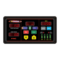
Figure 9. Detroit Diesel TGA302/402 Wiring
For DDEC VI 2007 and Newer Engines
ECU
J1939 CAN (+)
J1939 CAN (–)
V-43
V-58
Dk Blu/
Red
Dk Blu
DDEC
V
12-Pin
Connector
(Refer to
Figure 4)
Vehicle Interface
Harness Connector
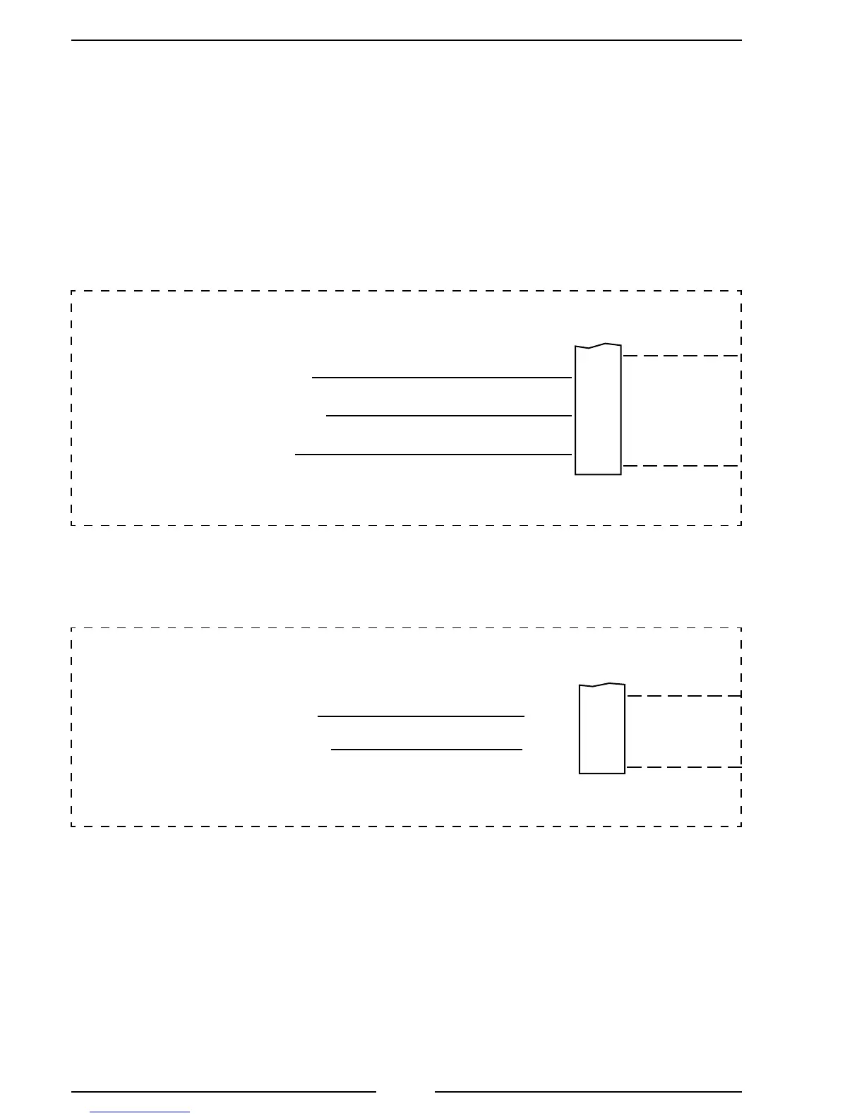
For DDEC V 2003 to 2006 Engines
ECU
J1939 CAN (–)
J1939 SHIELD
J1939 CAN (+)
DDEC
VI
Vehicle Interface Harness
18-Pin Connector #2
Pin 5 Black Wire
Pin 4 Red Wire
Pin 4 Red Wire
12-Pin
Connector
(Refer to
Figure 4)
Pin 5 Black Wire
2/16
2/17
2/18
Pin 12 Yellow Wire
Note: Refer to Figure 4. TGA 12-Pin Connector Wiring
for power and interlock wire connections.
 Loading...