TGA300 Rev180405
40
Scania Harness Connections—Type A
Interface Information
For use on P, R, and T-series trucks equipped with a bodywork control unit (BWS).
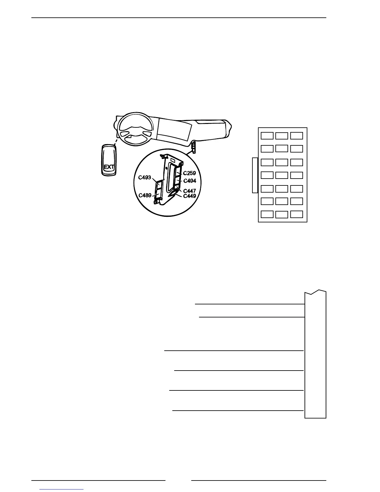
Connector C259 is available on all vehicles ordered with any of the bodywork options. It
is located on the plate for the electrical bodywork interface for body builders. Connector
C259 is white and has 21 pins. (February 2005 to 2015.)
Figure 16. Scania TGA308/408 Wiring—Type A
12 15 18 21
Contact Housing (MCP)
C259
3 6 9
12-Pin
Connector
(Refer to
Figure 4)
8-Pin
Connector
(Refer to
Figure 5)
C259
Connector
8
Engine RPM Control 2 +24 Volts
J1939 CAN high
21
9
Engine RPM Control 2 Earth
11
10
Engine RPM Control 2 Signal
Engine RPM Control 2 +5 Volts
J1939 CAN low
20
Note: Signal to pin 10 is 0.6 to 3.0 V
The EXT switch must be
in the ON position when
operating the INControl.
Note: Refer to Figure 4. TGA 12-Pin Connector Wiring
for power and interlock wire connections.
Pin 4 Red Wire
Pin 5 Black Wire
Pin 1 Red Wire
Pin 3 Orange Wire
Pin 2 Black Wire
Pin 8 Brown Wire
 Loading...