EasyManuals Logo
Home>FRC>Control Unit>InControl TGA400

FRC InControl TGA400 User Manual

Default Icon
52 pages
To Next Page IconTo Next Page
To Previous Page IconTo Previous Page
Page #45 background imageLoading...
Page #45 background image
TGA300 Rev180405
45
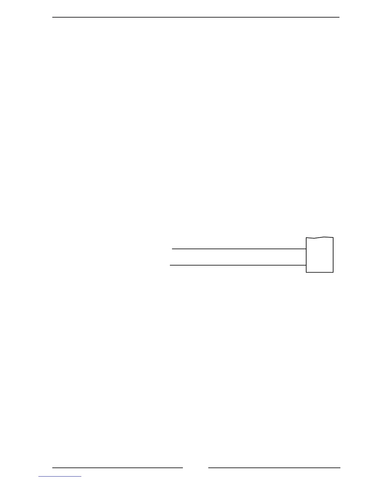
J1939 CAN Bus Control
X1997/18
X1997/17
J1939 (–)
J1939 (+)
Pin 9 Black Wire
Pin 10 Red Wire
12-Pin
Connector
(Refer to
Figure 4)
18-Pin Connector
X1997
Figure 20. MAN TGA324/424 Wiring
MAN Harness Connections
Interface Information
Parameters for various functions can be set on the KSM using MAN-cats II.
The KSM can accept the Engine speed request from the Governor on the A-CAN.
Note: Refer to Figure 4. TGA 12-Pin Connector Wiring
for power and interlock wire connections.
Brown-Orange/0.75 A-CAN-L
Orange/0.75 A-CAN-H

Table of Contents

Questions and Answers:

Question and Answer IconNeed help?

Do you have a question about the FRC InControl TGA400 and is the answer not in the manual?

FRC InControl TGA400 Specifications

General IconGeneral
BrandFRC
ModelInControl TGA400
CategoryControl Unit
LanguageEnglish

Related product manuals