SYSTEM CONFIGURATION
xvii
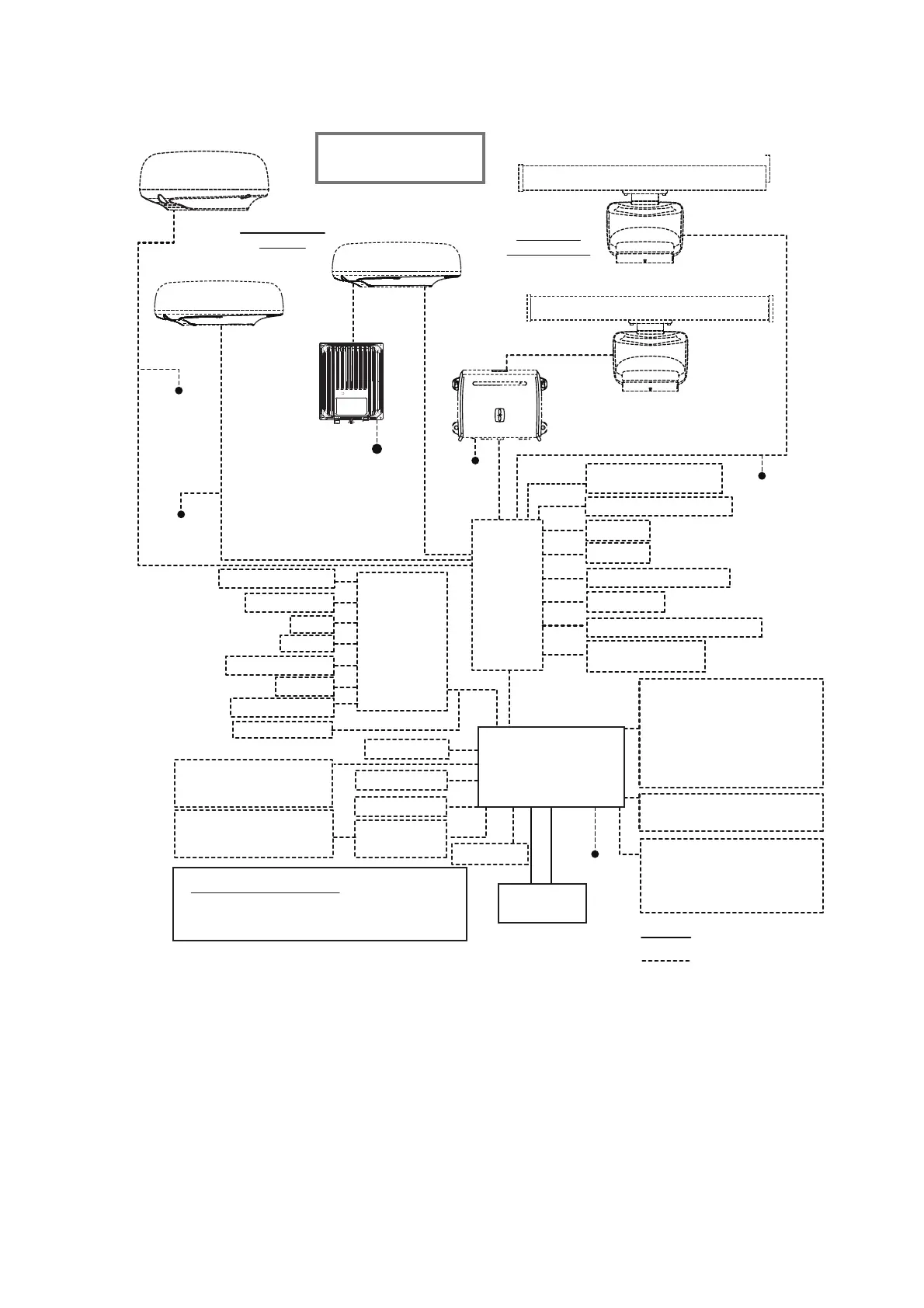
TZT2BB System Configuration
CCD Camera
CCD Camera
HDMI Input
12/24 VDC
Event SW
External Buzzer
NMEA0183 out
Power SW
Environmental category
Radar antenna: Exposed to the weather
All other units: Protected from the weather
*
1
Radar and required power supply unit.
DRS2D/4D/6A/12A: PSU-012; DRS25A/: PSU-013; DRS2D/4D: PSU-017
*
2
Max. 6 NavNet TZtouch2 units connected via Ethernet hub.
For configurations with TZT2BB included, a maximum of 4 NavNet TZtouch2 units
can be connected.
*
3
Hatteland Display monitor.
*
4
Use an after-market PoE hub. The NETGEAR GS108PE is confirmed as compatible. Compatibility tests are
limited to general use as part of this configuration and in no way indicates overall capability.
Further, FURUNO cannot guarantee the functionality of any after-market hub.
*
5
FURUNO networks allow for a maximum of three Ethernet Hub HUB-101s.
Exceeding this can result in undesirable results.
Display Unit (
Touch Monitor
*
3
)
HD19T21-MMD-MA1-FHGP,
HD19T22-MMD-MA1-FHGP,
HD24T21-MMD-MA1-FHGP
or
HD24T22-MMD-MA1-FHGP
Sub Display Unit
(Same models as above)
Remote Controller
MCU-002 or MCU-004
Processor Unit*
2
MPU-004
Transducer
Open Array
Radar Sensors
12-24 VDC
12-24 VDC
12-24 VDC
DRS2D, DRS4D
POWER SUPPLY UNIT*
1
PSU-012/PSU-013
Radome Radar
Sensors
DRS4A/DRS6A/DRS12A/DRS25A
POWER
SUPPLY
UNIT
*
1
PSU-017
DRS4DL, DRS4DL+
12-24 VDC
DRS4D-NXT
24 VDC
Select one of radome
or open array sensor.
: Standard supply
: Optional or local
supply
Switch Box
PSD-003
Remote Controller
MCU-005
PoE HUB*
4
Note: Do not connect/disconnect the HDMI cable between the MPU-004 and touch monitor while the power is
turned on.
IF-NMEA2K1/2
HUB -101*
5
FI-5002
SC-30
SCX-20
GP-33/GP-330B
FA-40/FA-70
NAVpilot Series
FI-50/70
AIS Transponder
(BBDS1, DFF series)
FA-30/50
FAX-30
FUSION-Link Equipment
BBWX weather receiver
Multi Beam Sonar
(DFF-3D)
IP Camera
FAR-2xx7/2xx8 series
FAR-15x3/15x8 series
DRS6A X-Class/DRS12A X-Class/DRS25A X-Class/
DRS6A-NXT/DRS12A-NXT
/
DRS25A-NXT
 Loading...