GE MEDICAL SYSTEMS
DIRECTION 2317229, REVISION 3 LOGIQ™ 180 BASIC SERVICE MANUAL
Chapter 5 Theory 5 - 5
5-2-1 PCB Nomenclature
The following table lists the Circuit boards on LOGIQ™ 180 system.
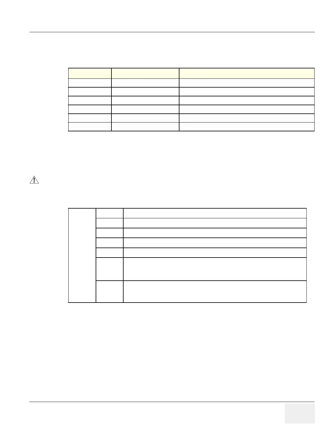
5-2-2 Dip Switch Setting
5-2-2-1 FEB Board
Table 5-14 Circuit board on LOGIQ™ 180
Board Abbrv Description Remarks
CPU Central Processing Unit For LOGIQ™ 180 (V7.0HC)
DSC Digital Scan Converter For LOGIQ™ 180 (V7.0HC)
KBD Keyboard For LOGIQ™ 180 (V7.0HC)
FEB Front End Board For LOGIQ™ 180 (V7.0HC)
PDB Power Distributor PCB For LOGIQ™ 180 (V7.0HC)
RLB Relay Board For LOGIQ™ 180 (V7.0HC)
CAUTION
The Settings are valid only when jumper JP1 and JP20 are in Test mode and is used for PCB
testing in the production line. The equipment at the customer site should have JP1 and JP20 in
normal mode which makes DIP switch S1 ineffective.
Table 5-15
S1 1 Probe Type 0
2 Probe Type 1
3 Probe Type 2
4 Probe Type 3
5 Probe Type 4
6 SDO (Shutdown 0)
0: Enables probe type indicator (Indicates probe is connected)
1: Disables probe type indication (Indicates probe is disconnected)
7 SD1 (Shutdown 1)
0: HV low (Not Used)
1: HV high (Not Used)
 Loading...


