GE MEDICAL SYSTEMS
D
IRECTION 2300164-100, REVISION 7 VIVID™ 3 PRO/VIVID™ 3 SERVICE MANUAL
5-26 Section 5-1 - Overview
Section 5-5
Back End Processor
5-5-1 Introduction
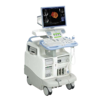
The Back End Processor (BEP) supports the operation of the Vivid™ 3 ultrasound unit and is the main
controller for the unit. The BEP comprises the various components described in the following sections:
•
Central Processing Unit (CPU) on page 5 - 31.
•
Keyboard Controller on page 5 - 34.
• Frame Grabber (RFI systems only) on page 5 - 35.
•
PC2IP on page 5 - 35.
•
Plug and Scan Card and Battery on page 5 - 35.
•
Network Onboard on page 5 - 35.-
•
SCSI Card on page 5 - 35.
•
Floppy Drive on page 5 - 36.
•
Hard Disk on page 5 - 36.
•
Magneto-Optical Drive (MOD) on page 5 - 37.
•
CD Read Write (CDRW) on page 5 - 37.
•
ECG Module on page 5 - 37
•
Modem on page 5 - 38.
•
PC-VIC Assembly on page 5 - 39.
Figure 5-19 on page 5-27 shows the location of the various components within the BEP for
BT02/BT03 systems with the RFI configuration. For systems with the RFT configuration, see
Figure 5-20 on page 5-28.
A block diagram of the BEP in Vivid™ 3 systems with the RFI configuration is provided in
Figure 5-21
on page 5-29. For systems with the RFT configuration, see Figure 5-22 on page 5-30.
Artisan Technology Group - Quality Instrumentation ... Guaranteed | (888) 88-SOURCE | www.artisantg.com
 Loading...