GE MEDICAL SYSTEMS
D
IRECTION 2300164-100, REVISION 7 VIVID™ 3 PRO/VIVID™ 3 SERVICE MANUAL
Chapter 5 - Components and Function (Theory) 5-43
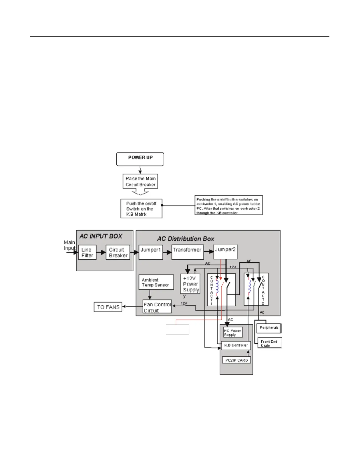
5-7-2 AC System
The AC System (see Figure 5-30) comprises the following components:
• AC Isolation Transformer.
• AC Distribution Box, as described in
AC Distribution Box on page 5 - 45.
• AC Input Box, see
AC Input Box on page 5 - 45.
• Thermal Fuses, see
Thermal Fuses on page 5 - 45.
Refer to
Figure 5-29 below for RFI-configured systems; for RFT-configured systems, see Figure 5-30
on page 5-44
.
Figure 5-29 AC System Block Diagram - RFI Configuration
Monitor
Monitor
230
230
110AC
Local voltage
230 AC
Artisan Technology Group - Quality Instrumentation ... Guaranteed | (888) 88-SOURCE | www.artisantg.com
 Loading...