GE MEDICAL SYSTEMS
D
IRECTION 2300164-100, REVISION 7 VIVID™ 3 PRO/VIVID™ 3 SERVICE MANUAL
Chapter 5 - Components and Function (Theory) 5-49
Section 5-8
Front End Cooling System
5-8-1 General Description
The Vivid™ 3 Front End cooling system includes following components:
• Dust Filter
• Fans
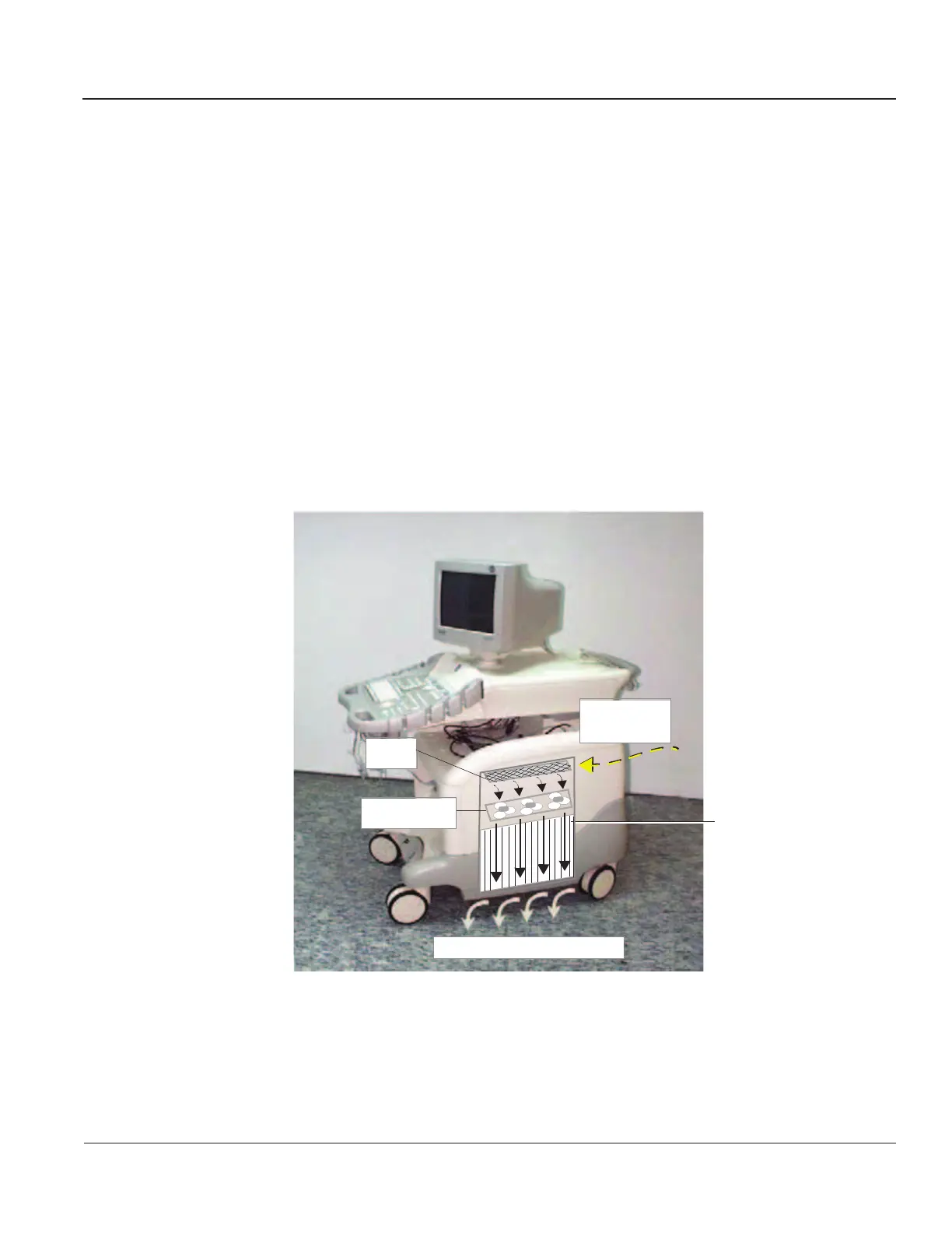
Other components that have an influence on the airflow is the Front End itself. Air is sucked from the
inside of the system through the Filter Cover and the Filter. It passes the Fan Assembly, directly into the
upper part of the Front End where it forms a cooling air current between the Boards, before being blown
out against the floor. See
Figure 5-34.
5-8-2 Location in the Unit
The Fan Assembly is located on top of the Front End Crate.
Figure 5-34 Airflow through the Vivid™ 3 System
Airflow through Board
Rack behind Side Cover
Filter
Fan Assembly
Air Inlet
through Filter
Air Outlet under the System
Artisan Technology Group - Quality Instrumentation ... Guaranteed | (888) 88-SOURCE | www.artisantg.com
 Loading...