Chapter 4 Wiring
The device supports connecng to the RS-485 terminal, the door lock, the exit buon, the alarm
output/input devices, the Wiegand card reader, the access controller, and the power supply. You
can wire the peripherals according to the
descripons below.
If connect the Wiegand card reader with the access controller, the face recognion terminal can
transmit the
authencaon informaon to the access controller and the access controller can
judge whether to open the door or not.
Note
If the cable size is 18 AWG, the distance between the power supply and the device should be no
more than 60 m when wiring a single device. And the door lock and the other peripherals should
connect to a 12 VDC external power supply. If connecng to a 12 VDC door lock, the distance
between the power supply and the device should be 30 m.
4.1 Terminal Descripon
The terminals contains power input, RS-485, Wiegand output, and door lock.
The descripons of the terminals are as follows:
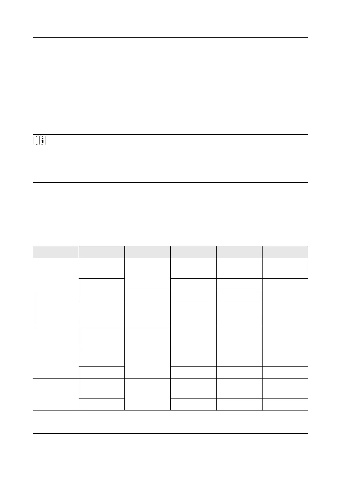
Table 4-1 Terminal
Descripons
Group No. Funcon Color Name Descripon
Group A A1 Power Input Red +12 V 12 VDC Power
Supply
A2 Black GND Ground
Group B B1 RS-485 Yellow 485+ RS-485 Wiring
B2 Blue 485-
B3 Red/Black GND Ground
Group C C1 Wiegand Green W0 Wiegand
Wiring 0
C2 White W1 Wiegand
Wiring 1
C3 White/Black GND Ground
Group D D1 Door Lock White/Purple NC Lock Wiring
(NC)
D2 White/Yellow COM Common
DS-K1T341B Series Face Recognion Terminal User Manual
12
 Loading...