208
Incoming/outgoing SA responses: 0/0
Incoming/outgoing data packets: 0/0
Inter-AS multicast configuration leveraging static RPF peers
Network requirements
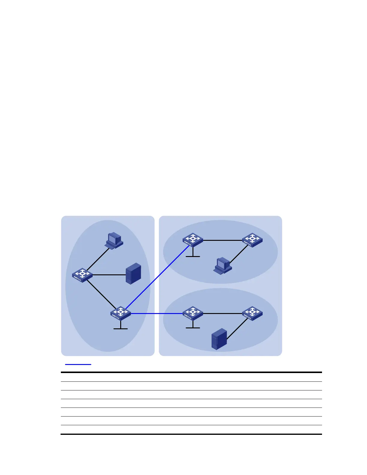
• As shown in Figure 59, AS 100 and AS 200 run OSPF within each AS, and run BGP between
each other.
• PIM-SM 1 belongs to AS 100, and PIM-SM 2 and PIM-SM 3 belong to AS 200.
• Each PIM-SM domain has zero or one multicast source and receiver. OSPF runs within each
domain to provide unicast routes.
• PIM-SM 2 and PIM-SM 3 are both stub domains, and BGP or MBGP is not required between these
two domains and PIM-SM 1. Instead, static RPF peers are configured to avoid RPF check on SA
messages.
• Loopback 0 of Switch B, Switch C, and Switch E must be configured as the C-BSR and C-RP of the
PIM-SM domains respectively.
• Switch C and Switch E must be configured as static RPF peers of Switch B, and Switch B must be
configured as the only static RPF peer of Switch C and Switch E, so that any switch can receive SA
messages from only its static RPF peers and permitted by the corresponding filtering policy.
Figure 59 Network diagram for inter-AS multicast configuration leveraging static RPF peers
Vlan-int101
Vlan-int10
2
Switch B
Switch A
Source 1
AS 100
PIM-SM 1
PIM-SM 3
PIM-SM 2
Loop0
Switch C
Switch D
Switch E
Switch F
Source 2
Vlan-int100
Vlan-int103
Vlan-int101
Vlan-int104
Vlan-int105
Loop0
Receiver
Receiver
Loop0
Static RPF peers
Vlan-
i
nt1
03
Vlan-in
t2
00
Vlan-int104
Vlan-int105
Vl
a
n-
int300
Vlan-int40
0
AS 200
Vlan-
i
nt1
0
2
Device Interface IP address Device Interface IP address
Switch A Vlan-int103 10.110.1.2/24 Switch D Vlan-int104 10.110.4.2/24
Vlan-int100 10.110.2.1/24 Vlan-int300 10.110.5.1/24
Vlan-int200 10.110.3.1/24 Switch E Vlan-int105 10.110.6.1/24
Switch B Vlan-int103 10.110.1.1/24 Vlan-int102 192.168.3.2/24
Vlan-int101 192.168.1.1/24 Loop0 3.3.3.3/32
Vlan-int102 192.168.3.1/24 Switch F Vlan-int105 10.110.6.2/24
 Loading...


