379
IPv6 PIM-SM non-scoped zone configuration example
Network requirements
• Receivers receive VOD information through multicast. The receiver groups of different organizations
form stub networks, and one or more receiver hosts exist in each stub network. The entire PIM
domain operates in the sparse mode.
• Host A and Host C are IPv6 multicast receivers in two stub networks, N1 and N2.
• Switch D connects to the network that comprises the IPv6 multicast source through VLAN-interface
300.
• Switch A connects to N1 through VLAN-interface 100 and to Switch D and Switch E through VLAN-
interface 101 and VLAN-interface 102, respectively.
• Switch B and Switch C connect to N2 through their respective VLAN-interface 200, and to Switch E
through VLAN-interface 103 and VLAN-interface 104 respectively.
• VLAN-interface 105 on Switch D and VLAN-interface 102 on Switch E act as C-BSRs and C-RPs.
The C-BSR on Switch E has a higher priority. The IPv6 multicast group range served by the C-RP is
FF0E::101/64. Modify the hash mask length to map a certain number of consecutive IPv6 group
addresses within the range to the two C-RPs.
• MLDv1 will run between Switch A and N1 and between Switch B/Switch C and N2.
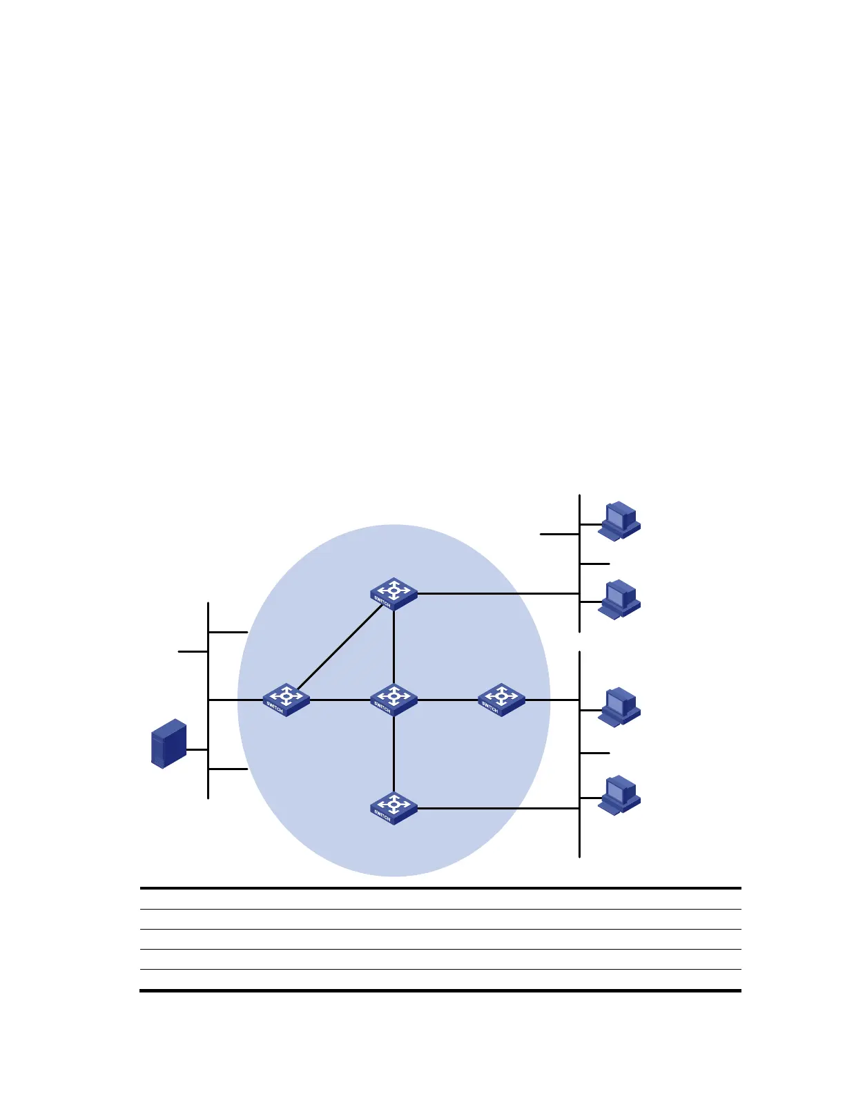
Figure 100 Network diagram for IPv6 PIM-SM non-scoped zone configuration
Ethernet
EthernetEthernet
Source
4001::100/64
IPv6 PIM-SM
Switch A
Switch B
Switch C
Switch D
Receiver
Host A
Host B
Host C
Host D
Receiver
N1N2
Switch E
Vlan-int100
Vlan-int200
Vlan-int200
Vlan-int300
Vlan-int102
Vlan-int102
Vlan-in
t1
01
Vlan-
int10
1
Vlan-int103
Vlan-int103
Vlan-int104
Vlan-int104
Vlan-int105
Vlan-int105
Device Interface IP address Device Interface IP address
Switch A Vlan-int100 1001::1/64 Switch D Vlan-int300 4001::1/64
Vlan-int101 1002::1/64 Vlan-int101 1002::2/64
Vlan-int102 1003::1/64 Vlan-int105 4002::1/64
Switch B Vlan-int200 2001::1/64 Switch E Vlan-int104 3001::2/64
 Loading...


