236
MBGP configuration example
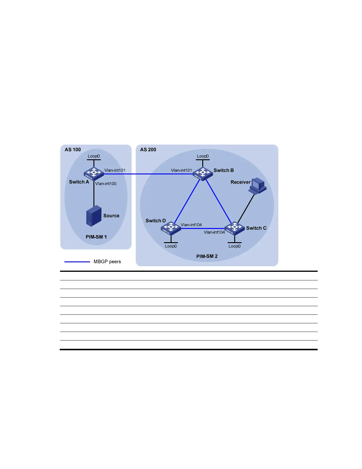
Network requirements
As shown in Figure 62:
• PIM-SM 1 is in AS 100, and PIM-SM 2 is in AS 200. OSPF is the IGP in the two ASs, and MBGP
runs between the two ASs to exchange multicast route information.
• The multicast source belongs to PIM-SM 1, and the receiver belongs to PIM-SM 2.
• Configure Loopback 0 of Switch A and Switch B as the C-BSR and C-RP of the respective PIM-SM
domains.
• Set up an MSDP peer relationship through MBGP between Switch A and Switch B.
Figure 62 Network diagram for MBGP configuration
V
l
a
n
-i
n
t
1
0
2
V
l
a
n
-
i
n
t
1
0
3
V
l
a
n
-
i
n
t
1
0
3
V
l
a
n
-
i
n
t
1
0
2
V
l
a
n
-
i
n
t
2
0
0
Device Interface IP address Device Interface IP address
Source - 10.110.1.100/24 Switch C Vlan-int200 10.110.2.1/24
Switch A Vlan-int100 10.110.1.1/24 Vlan-int102 192.168.2.2/24
Vlan-int101 192.168.1.1/24 Vlan-int104 192.168.4.1/24
Loop0 1.1.1.1/32 Loop0 3.3.3.3/32
Switch B Vlan-int101 192.168.1.2/24 Switch D Vlan-int103 192.168.3.2/24
Vlan-int102 192.168.2.1/24 Vlan-int104 192.168.4.2/24
Vlan-int103 192.168.3.1/24 Loop0 4.4.4.4/32
Loop0 2.2.2.2/32
Configuration procedure
1. Configure IP addresses for interfaces as shown in Figure 62 (details not shown).
2. Configure OSPF (details not shown).
3. Enable IP multicast routing, PIM-SM and IGMP, and configure a PIM-SM domain border.
# Enable IP multicast routing on Switch A, and enable PIM-SM on each interface.
<SwitchA> system-view
[SwitchA] multicast routing-enable
 Loading...


