72 Chapter3
Remove/Replace System Components
Removing/Replacing System Components
Removing the System Board
To remove the system board, follow this procedure:
1. Complete the procedure in the section “Removing the CD Drive” (steps 1 through
3; in this chapter), “Removing the DAT Drive” (steps 1 through 5; in Appendix
F), or “Removing the Flexible Disk Drive” (steps 1 through 5; in Appendix G).
2. Complete the procedure in the section “Removing the PCI Cage, I/O Card and PCI
Backplane Board” found in this chapter.
3. Complete the procedure in the section “Removing the Hard Disk Drive(s)” found in
this chapter.
4. Complete the procedure in the section “Removing the AC or DC Power Supply”
found in this chapter.
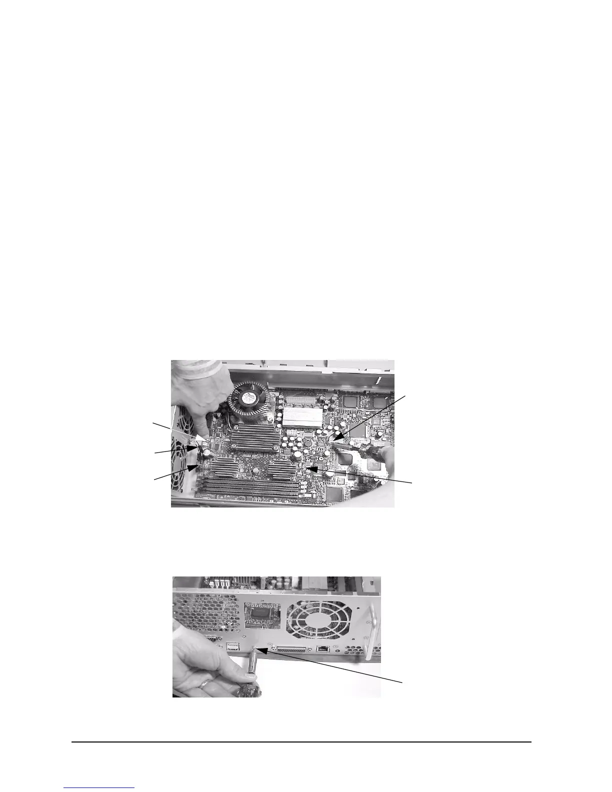
5. Disconnect the two fan power connectors from the system board by pressing in on the
latch retainers and pulling outward on the connector. The LCD connector must also be
disconnect from the system board by pressing down on its latch retainers and pulling
outward on the connector. Next, unscrew the two internal system board mounting
screws. See Figure 3-53.
Figure 3-53. Removing the Internal System Board Mounting Screws
6. Unscrew the rear mounting screw for the system board. See Figure 3-54.
Figure 3-54. Removing the System Boards Rear Mounting Screw
System Board
Mounting Screw
System Board
Mounting Screw
System Board
Two Fan Power
Connectors
LCD Connector
Rear Mounting Screw
 Loading...