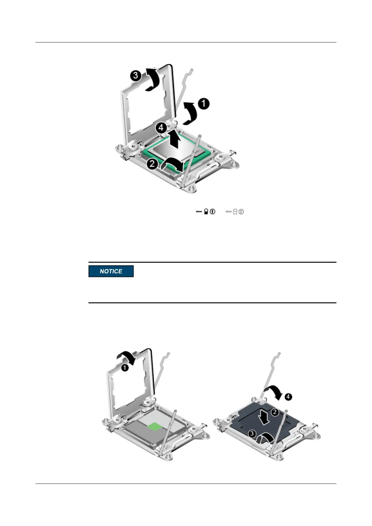
Figure 7-73 Removing a v4 series CPU
b. Raise the securing rod near the or label. See step (2) in Figure 7-73.
c. Lift the load plate to a fully open position, and remove the CPU from the socket.
See steps (3) and (4) in Figure 7-73.
d. Place the removed CPU in an ESD bag.
Ensure that CPU sockets are populated with CPUs or CPU protective covers during
transportation and storage.
Step 13 (Optional) Install a CPU protective cover.
1. Close the CPU load plate. See step (1) in Figure 7-74.
Figure 7-74 Installing a CPU protective cover
RH2288 V3 Server
User Guide
7 Replacing Parts
Issue 32 (2019-03-28) Copyright © Huawei Technologies Co., Ltd. 197

 Loading...