62 Chapter 5: Before you unplug and open the tower
4. Touch the bare metal frame of your tower to
dissipate the static electricity from your body. Do
not touch any of the components inside the frame
before you touch the frame. Be careful not to touch
any component displaying a voltage warning label,
such as the power supply.
5. Disconnect the tower power cord.
Inside the tower
So that you can recognize the smaller hardware
components in your Aptiva computer, you need to know
the location of the following major hardware
components inside your tower:
System board
The system board has a socket for the processor,
also known as the central processing unit (CPU). It
also has sockets for drive cable connectors,
memory modules, the system battery, and the
riser card.
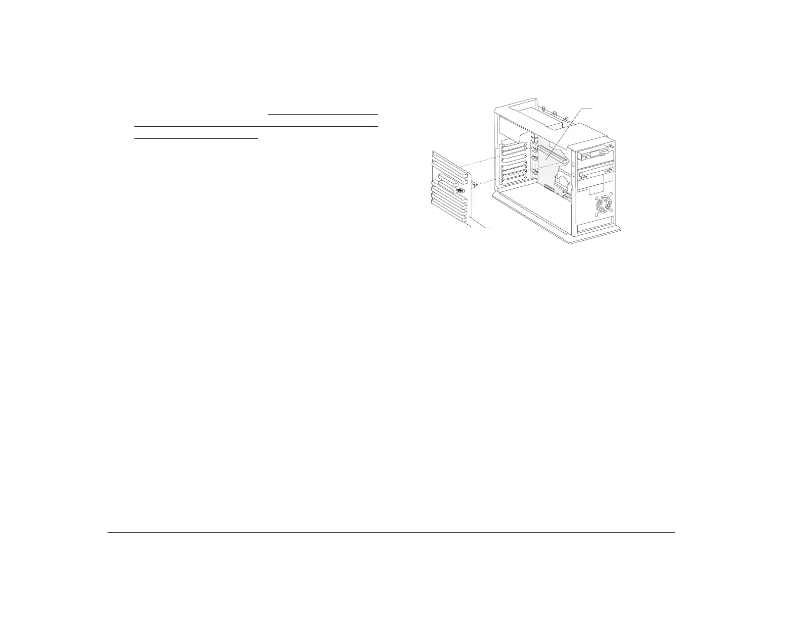
Riser card
The riser card has connectors for adapter cards.
Inside the tower, the system board is positioned up
against the right wall. The riser card is attached to the
system board, parallel and very close to the system
board.
With the tower cover removed, the tower looks like this:
If you plan to work with the hardware inside your tower,
read “Planning your hardware changes” on page 56 and
“Opening the tower” on page 61 before you remove the
tower cover.
Riser
Card
(Removed)
System Board