5
1
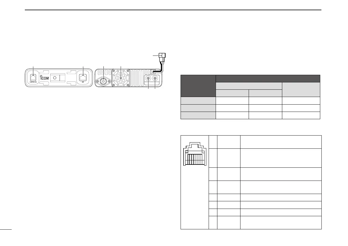
PANEL DESCRIPTION
New2001 New2001
■ Main unit
q CONTROLLER CONNECTOR [CONTROLLER] (p. 63)
Connects to the Controller using the supplied control cable.
w MICROPHONE CONNECTOR [MIC]
Plug in the supplied HM-207 microphone or the optional
HM-154 microphone.
e ANTENNA CONNECTOR (p. 67)
Connect a 50 ø impedance antenna with a PL-259 con-
nector.
The transceiver has a built-in duplexer, so you can use a
144 and 430 MHz dual-band antenna without needing an
external duplexer.
r COOLING FAN
The cooling fan for heat dissipation.
You can select the Fan control option in EXMENU, to au-
tomatically start rotating when you begin transmitting, or
continuously rotate from power ON. (p. 14)
t DC POWER SOCKET [DC 13.8V]
Connect a 13.8 V DC power source through the supplied
DC power cable.
y EXTERNAL SPEAKER JACK 2 [SP2]
u EXTERNAL SPEAKER JACK 1 [SP1]
Connect an 8 ohm external speaker.
•Seethefollowinglistforthespeakerconnectionandaudioout-
put details.
Ext. speaker
connection
status
Audio output
External speaker
Internal speaker
SP-1 SP-2
SP-1 and SP-2 Left band Right band –
SP-1 only Both bands – –
SP-2 only – Right band Left band
D Microphone connector information
Front panel
view
1 8 V +8 V DC output
Maximum 10 mA
2 MIC U/D Frequency Up/Down
UP: Ground
DN: Ground through 470 ˘
3 M8V SW HM-207 connection
Grounds when the HM-207 is connected.
4 PTT PTT input
Ground for transmission
5 MIC E Microphone ground
6 MIC Microphone input
7 GND PTT ground
8 DATA IN
Inputs HM-207 data when the HM-207
is connected.
q w e r
t
yu
Front panel Rear panel
 Loading...