IS620P User Manual Chapter 3 Wiring of Servo System
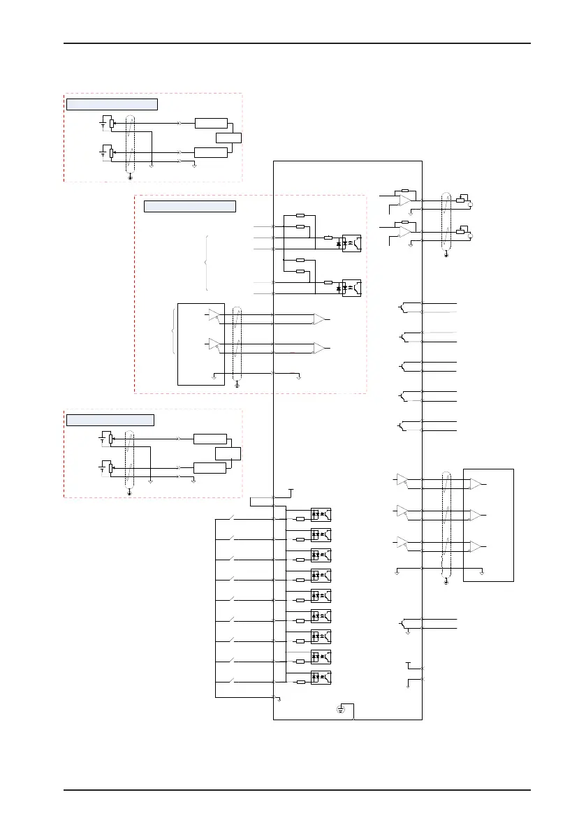
Servo drive
PE shield connected to
housing of the connector
GND
AO1
GND
AO2
A
A
Encoder frequency-division
pulse differential output
PAO-
PAO+
21
22
PBO-
PBO+
25
23
PZO-
PZO+
13
24
Phase Z
output
Phase A
output
Phase B
output
29
GND
GND
PZ-OUT
GND
44
29
Encoder phase Z
OC output
GND
29
15
GND
+5V
GND
5V
DI1
24V
COM+
9
11
17
+24 V
power
4.7 kΩ
4.7 kΩ
4.7 kΩ
4.7 kΩ
4.7 kΩ
4.7 kΩ
4.7 kΩ
4.7 kΩ
4.7 kΩ
DI2
10
DI3
34
DI4
8
DI5
33
DI6
32
DI7
31
DI8
30
DI9
12
COM-
14
Low-speed pulse
position reference
PULSE+
PULSE-
PULS
[
CW phase A
]
35
Interface of internal 24 V power
for open-collector output
41
43
240 Ω
PULLHI
2.4 kΩ
2.4 kΩ
SIGN+
SIGN-
SIGN
[
CW phase B
]
37
39
240 Ω
2.4 kΩ
2.4 kΩ
HPULSE
[CW phase A]
High-speed
pulse position
reference
(max. 4 MHz)
HPULSE+
38
HPULSE-
36
29
Note 2
HSIGN+
42
HSIGN-
40
HSIGN
[CCW phase B]
GND
GND
Standard wiring in position control mode
DO2+
5
4 DO2-
DO1+
7
6
DO1-
DO3+
3
2
DO3-
DO4+
1
26
DO4-
DO5+
28
27
DO5-
Analog speed
AI1
20
AI2
18
GND
19
Low-pass filter
A
/D
converter
Low-pass filter
Standard wiring in speed control mode
Analog torque
Max. forward
analog speed limit
AI1
20
AI2
18
GND
19
Low-pass filter
A/D
converter
Low-pass filter
Standard wiring in torque control mode
Max. forward
analog speed limit
 Loading...
