IS620P User Manual Chapter 3 Wiring of Servo System
- 61 -
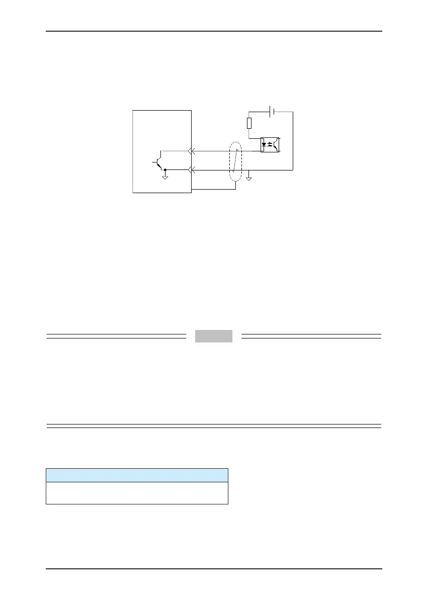
Encoder phase Z output circuit outputs OC signals. Normally, the encoder phase Z output
circuit provides feedback signals to the host controller. The circuit and the host controller
together form a closed-loop position control system. An optocoupler circuit, relay circuit, or bus
receiver circuit shall be used in the host controller to receive feedback signals.
GND
Servo drive
5-24 VDC
Optocoupler
29
PZ-OUT
GND
44
PE
To reduce noise interference, connect the 5V ground of the host controller to the GND terminal
of the servo drive, and use the shielded twisted-pair.
The maximum allowable voltage and current of the optocoupler output circuit inside the servo
drive are as below:
•
Maximum voltage: 30 VDC
•
Maximum current: DC, 50 mA
3.3.5 Wiring of Holding Brake
The holding brake is used when the servo motor controls a vertical shaft. The servo motor with
brake prevents the movable part from shifting due to gravity when the power supply fails.
•
The holding brake built in the servo motor is only used for keeping the stopped state. Do not use it
to stop running of the servo motor.
•
Brake coils are of no polarity.
•
When the servo motor with brake runs, the brake may generate click sound, which does not affect
its functions.
•
When brake coils are energized (the brake is ON), magnetic ux leakage may occur at the shaft
end. Thus, pay special attention when using magnetic sensors around the servo motor.
The following table describes the models of holding brake connectors.
Table 3-17 Models of holding brake connectors for frame 40/60/80 servo motor
2-pin plug, regardless of positive or negative polarity
Plastic housing: AMP 172157-1
Terminal: AMP 770835-1
 Loading...
