Chapter 4 Running and Commissioning IS620P User Manual
- 86 -
The following table takes AI2 as an example to describe the analog setting of the speed
reference.
Table 4-4 Analog setting of speed reference
Step Operation Remarks
1
Set H06-00 (Main speed reference A source) to
2 (AI2), and H06-02 (Keypad setting value of
speed reference) to 0 (Digital setting).
Set the speed reference source in the
speed control mode.
2
Set related parameters of AI2.
a. Zero drift correction (set in H03-59 or auto
correction in H0D-10)
b. Offset setting (H03-55)
c. Dead zone setting (H03-58)
Adjust AI2 sampling by setting the zero
drift, offset, and dead zone.
3
Set H03-80 (Speed corresponding to 10 V) to
3000 RPM.
Set the maximum speed (value of H03-
80) corresponding to +10 V.
Set the minimum speed (negative value
of H03-80) corresponding to -10 V.
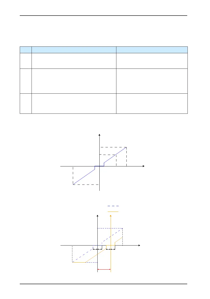
When there is interference on the AI2 input signal, set the AI2 input lter time (H03-56).
Figure 4-7 No-offset AI2
V_Ref
AI
Speed
Voltage
Speed corresponding to
+10 V (+H03-80)
Speed corresponding
to -10 V (-H03-80)
+10 V
-10 V
Dead zone
(H03-58)
Figure 4-8 After-offset AI2
Voltage
Offset
(H03-55)
Speed corresponding
to -10 V (-H03-80)
Dead zone
(H03-58)
-10 V
+10 V
Speed corresponding
to +10 V
Speed
(After offset)
Speed
(No-offset)
No-offset speed
reference curve
After-offset speed
reference curve
 Loading...
