IS620P User Manual Chapter 3 Wiring of Servo System
- 57 -
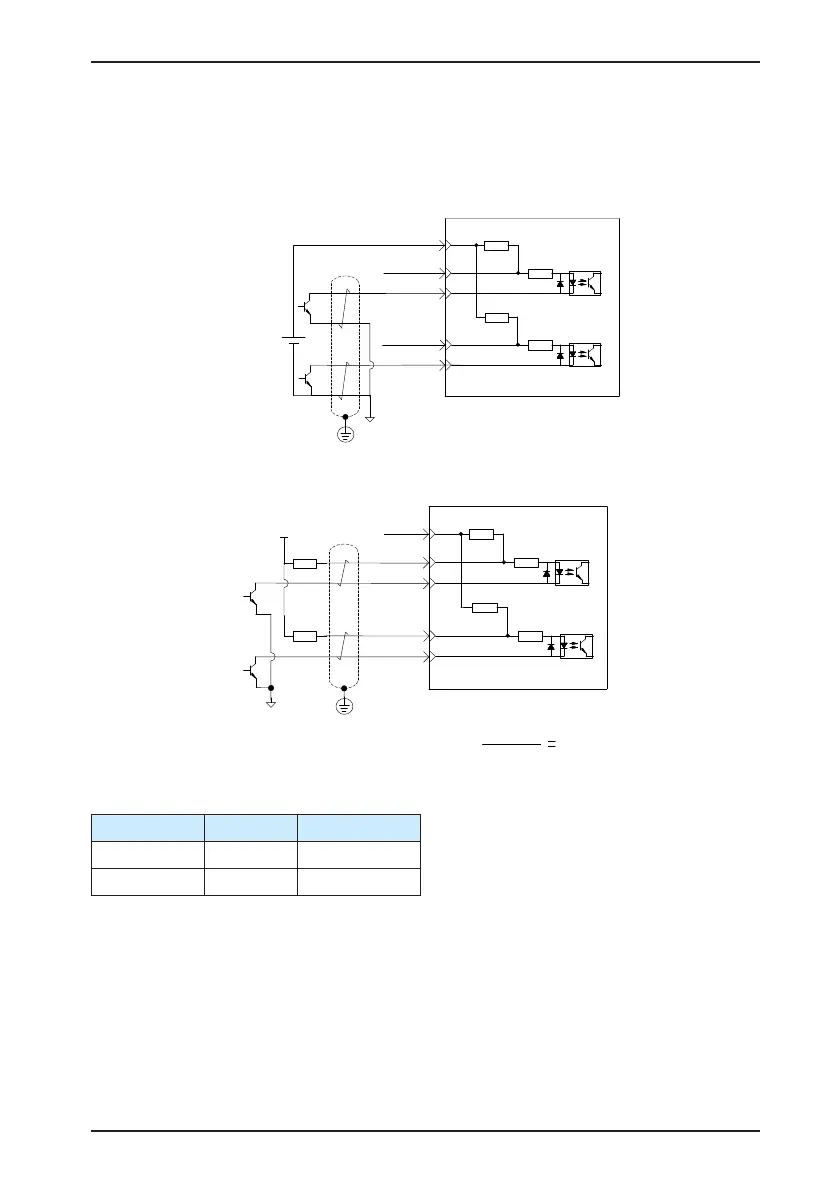
The following two gures show the wiring method when the external 24 V power supply is
used.
1) Using internal resistor of the servo drive (recommended)
Servo drive
PULSE+
PULSE-
35
41
43
240 Ω
PULLHI
SIGN+
SIGN-
37
39
240 Ω
2.4 kΩ
2.4 kΩ
External
24 VDC
COM
OC pulse position reference:
Min. pulse width: 2.5 us
Max. input frequency: 200 kpps
2) Using external current-limit resistor
Servo drive
PULSE+
PULSE-
35
41
43
240 Ω
PULLHI
SIGN+
SIGN-
37
39
240 Ω
2.4 kΩ
2.4 kΩ
COM
R1
R1
VCC
Value of resistor R1 shall satisfy the following formula:
Table 3-16 Recommended R1 resistance
V
CC
Voltage
R1 Power of R1
24 V 2.4 kΩ 0.5 W
12 V 1.5 kΩ 0.5 W
 Loading...
