6. Description of Parameters
- 130 -
■
V/F Separation Curve
Function Code Parameter Name Setting Range Default
F3-13
Voltage source for V/F
separation
0: Set by F3-14
1: AI1
2: AI2
3: AI3
4: Pulse reference (DI5)
5: Multi-reference
6: Simple PLC
7: PID reference
8: Serial comms.
100.0% corresponds to the rated
motor voltage (F1-02, A2-02).
0
F3-14
Digital setting of voltage
for V/F separation
0 V to rated motor voltage 0 V
F3-15
Voltage rise time of V/F
separation
0.0s to 1000.0s 0.0s
F3-16
Voltage decline time of
V/F separation
0.0s to 1000.0s 0.0s
F3-17
Stop mode selection for
V/F separation
0: Frequency and voltage
declining to 0 independently
1: Frequency declining after
voltage declines to 0
0
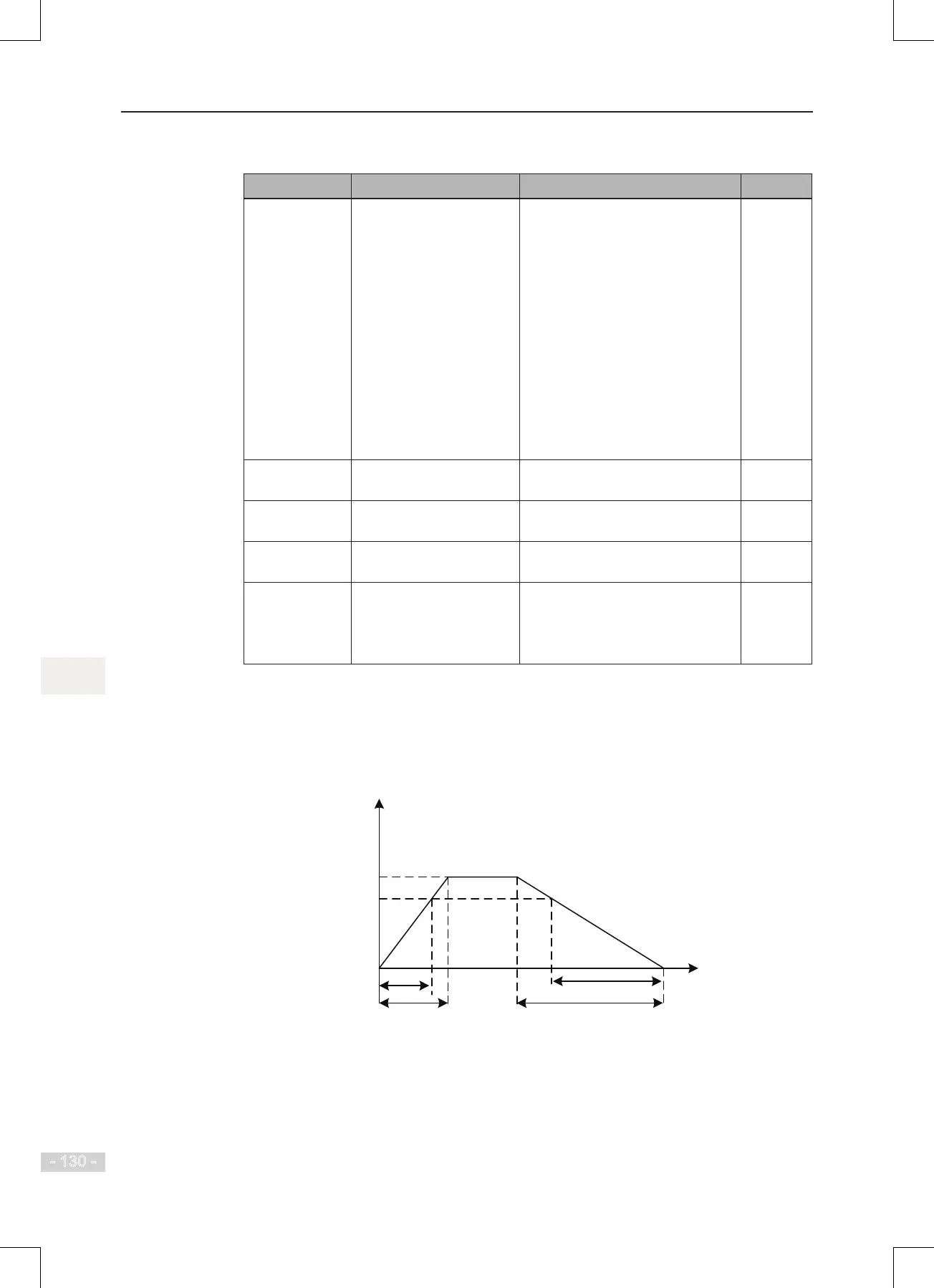
Voltage rise time of V/F separation indicates time required by voltage to rise from 0 to
rated motor voltage.
Voltage decline time of V/F separation indicates time required by voltage to decline from
rated motor voltage to 0.
Figure 6-39 V/F separation
Output voltage
F1-02
(Rated motor voltage)
Target voltage
Actual voltage rise time
Set voltage rise time
t1 (F3-15)
t2 (F3-16)
Actual voltage decline time
Set voltage decline time
 Loading...
