6. Description of Parameters
- 156 -
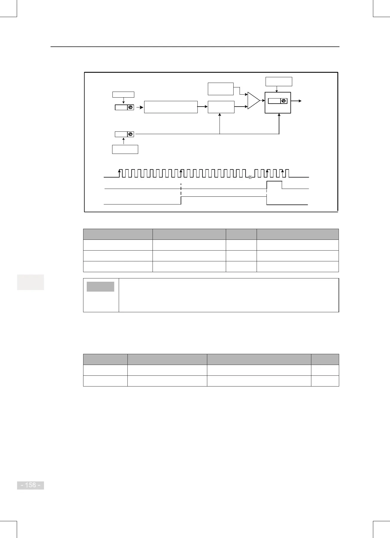
Figure 6-50 Fixed length control
DI5
DIx
Allocate DI5 with the length
signal pulses counting function.
F4-04 = 27
Any of F4-04
to F4-09 = 28
Allocate DIx with the
length reset function.
=
Fb-06
Actual length
Fb-05
Set length
Clear to 0
≥
Compare
DO
Any of F5-00
to F5-05 = 10
Reset
Allocate DO with the
length reached function.
DO outputs the length
reached signal.
Length reset input
Length reached output
Length pulses input
1 2 3 10 11 12
1 2
Fb-06 = 0
Fb-06 = 11
Fb-05 = 11
U0-13 = 0
Number of sampled pulses / Fb-
07 (Number of pulses per meter)
Settings of related function parameters in the preceding gure are as follows:
Function Code Parameter Name Setting Description
F4-04 DI5 function selection 27 Length pulses counting input
Any of F4-00 to F4-09 DIx function selection 28 Length reset
Any of F5-00 to F5-05 DOx function selection 10 Length reached
● Only length can be calculated according the number of pulses but rotation
direction will not be obtained in xed length control.
● An automatic stop system can be implementing by connecting output length
reached signal of relay to the stop input terminal.
6.8.3 Counting
The drive has the counting function. The sampling DI terminal must be set for function 25
"Counter input ". For high pulse frequency, use terminal DI5.
Function Code Parameter Name Setting Range Default
Fb-08
Set count value 1 to 65535 1000
Fb-09
Designated count value 1 to 65535 1000
In the following figure, When the counting value reaches the level set in Fb-08, digital output
terminal set for function 8 "Set count value reached" becomes on. When the counting value
reaches the level set in Fb-09, digital output terminal set for function 9 "Designated count value
reached" becomes on.
 Loading...
