3. Electrical Installation
- 50 -
■
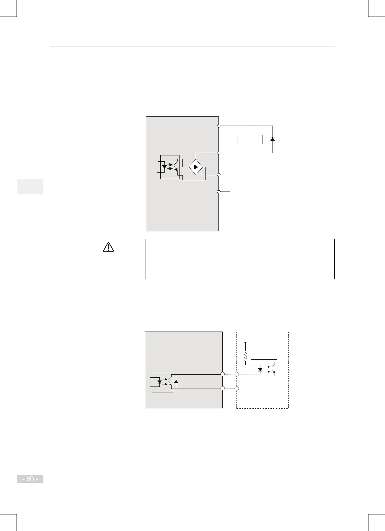
Wiring of DO
When digital output terminal must drive relay, it is necessary to install an absorption diode
across relay coil. This diode prevents inductive switching transients causing damage to
the DC 24V power supply. The absorption diode must have a forward current rating of 50
mA.
Figure 3-16 Wiring of digital output terminal
DO
CME
COM
Relay Diode
MD500
+24V
● Be careful to install absorption diode with correct polarity, to prevent
damage to the 24 VDC power supply.
● CME and COM are internally insulated, but are shorted externally by
a jumper. In this case, DO1 is driven by+24 V by default. Remove the
jumper if you need to drive DO1 by an external power supply.
■
Wiring of High-speed Output FM
When the FM terminal is used for continuous pulse output, maximum output frequency is
100 kHz.
Figure 3-17 Wiring of high-speed output terminal FM
FM
COM
VCC
0V
External controller
MD500
 Loading...
