7. Interfaces and Communication
- 203 -
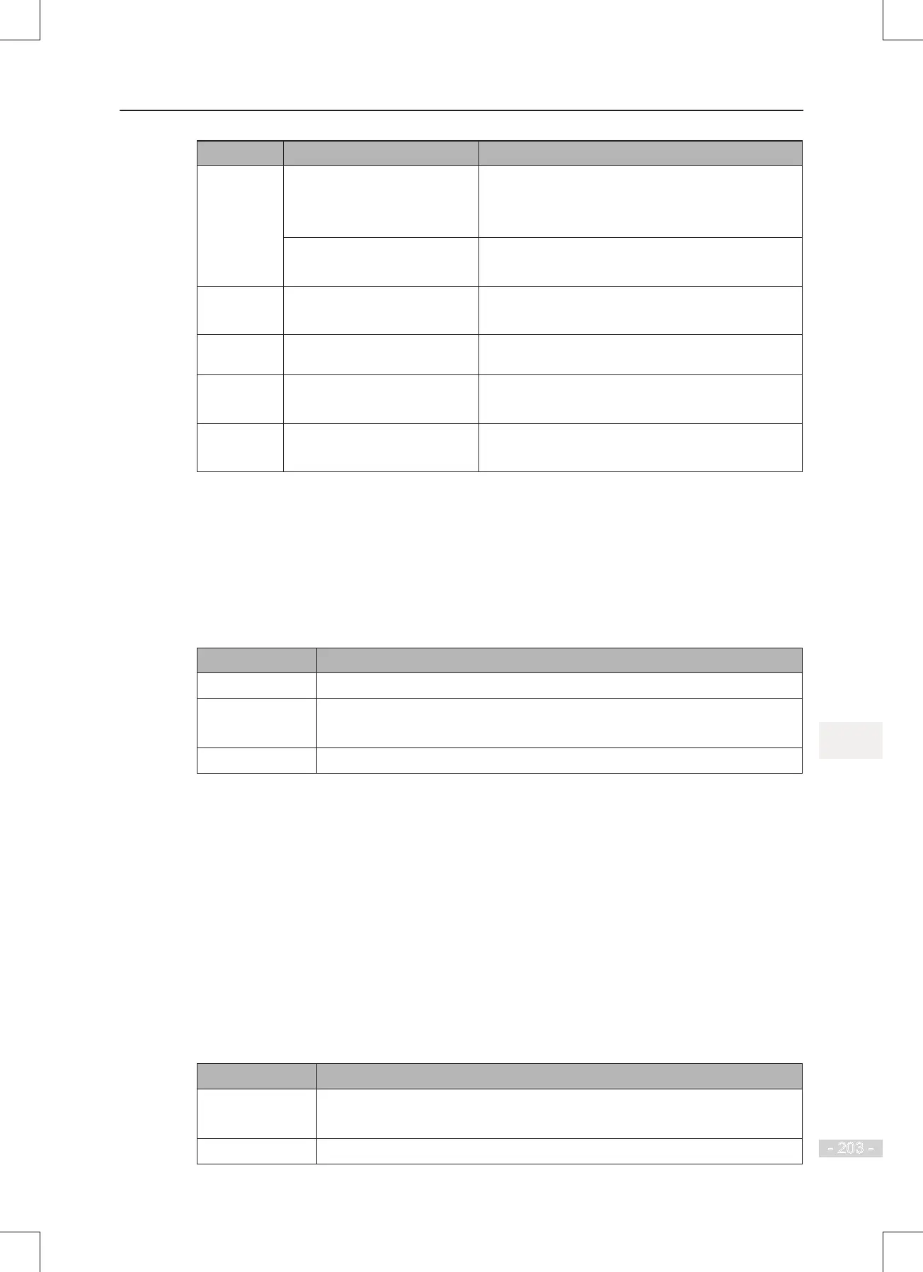
Terminal Corresponding Function Code Output Feature Description
FM-CME F5-06 when F5-00 = 0 Transistor
Able to output high-speed pulses 10 Hz to 100 KHz
Drive capacity: 24 VDC, 50 mA
F5-01 when F5-00 = 1 Transistor
Drive capacity: 24 VDC, 50 mA
TA-TB-TC F5-02 Relay
Drive capacity: 50 VAC, 0.2 A/30 VDC, 1 A
PA-PB-PC F5-03 Extension card, relay; drive capacity: 50 VAC, 0.2
A/30 VDC, 1 A
DO1-CME F5-04 Transistor
Drive capacity: 24 VDC, 50 mA
DO2-CME F5-05 Extension card transistor
Drive capacity: 24 VDC, 50 mA
When F5-00 = 0, FM terminal is high-speed pulse output. Frequency of pulses on this DO
terminal indicates the value of internal running parameters. Higher values of internal running
parameters produce higher pulse frequencies. Value 100% corresponds to a pulse frequency of
100 kHz.
■
Use of AI Terminals
The drive supports a maximum of three analog input terminals. Of these, AI1 and AI2 are on the
control board, and AI3 is on the optional extension card.
Terminal Input Signal Characteristic
AI1-GND It receives the signal of 0 to 10 VDC.
AI2-GND
If J9 jumps to the "V" position, AI receives voltage signal of 0 to 10 VDC.
If J9 jumps to the "I" position, AI receives current signal of 0 to 20 mA.
AI3-GND It receives signal of -10 to 10 VDC.
Analog inputs allow an external voltage or current signal to set frequency reference, torque
reference, voltage setting at V/F separation, and PID reference and feedback. F4-13 to F4-27
dene relationship between analog input voltage or current signals and actual controlled setting
or feedback.
Sampling of analog values on AI terminals is possible by reading function codes:
● U0-09 shows value of AI1.
● U0-10 shows value of AI2.
● U0-11 shows value of AI3.
■
Use of AO Terminals
The drive supports a maximum of two analog output terminals. AO1 is on the control board and
AO2 is on the optional extension card.
Terminal Input Signal Characteristic
AO1-GND
If J5 jumps to the "V" position, AO outputs voltage signal of 0 to 10 VDC.
If J5 jumps to the "I" position, AO outputs current signal of 0 to 20 mA.
AO2-GND It outputs voltage signal of 0 to 10 VDC.
 Loading...
