3. Electrical Installation
- 51 -
■
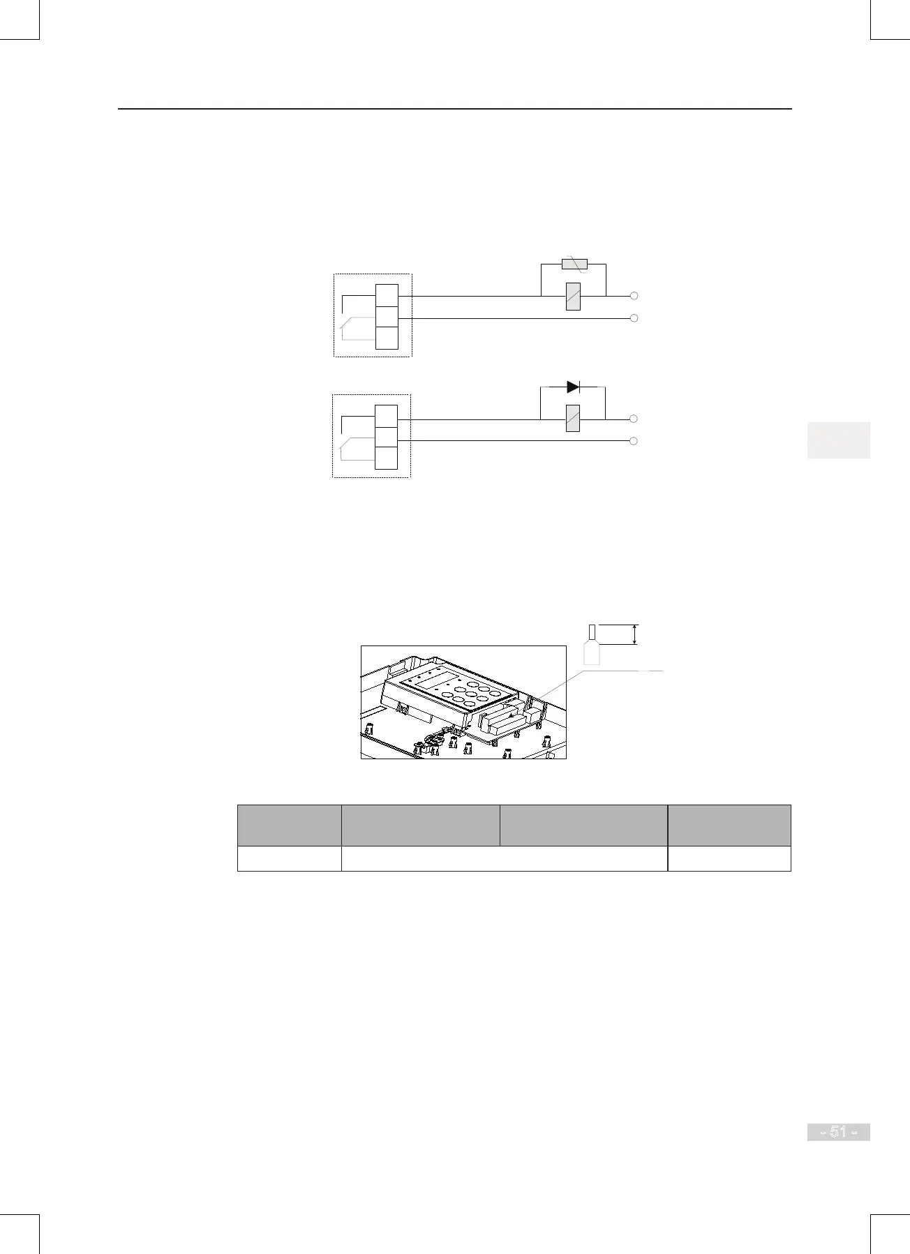
Wiring of Relay
To smooth peak voltage that results from cutting off power to inductive load (relay,
contactor and motor), use a voltage dependent resistor (VDR) at the relay contact and
add absorbing circuit to the inductive load, such as VDR, RC absorbing circuit or diode.
Figure 3-18 Wiring of relay
220 VAC
24 VDC
T/C
T/A
T/B
T/C
T/A
T/B
■
Wire Size and Torque Specication
Please use a ferrule-type terminal with insulated sleeves. Prepare wire ends with
insulated sleeves before connecting to the drive. See
F
i
g
u
r
e
3
-
2
3
F
e
r
r
u
l
e
d
i
m
e
n
s
i
o
n
s
below.
Figure 3-19 Ferrule dimensions
Table 3-10 Wire size and torque specication
Terminal Block Single Wire (AWG/mm
2
) Twisted Wire (AWG/mm
2
) Tightening Torque
(N·m)
Control circuit AWG 24 to 18 (0.2 to 0.75 mm
2
) 0.8 to 1.0
 Loading...
